Toyota Tacoma (2015-2018) Service Manual: On-vehicle Inspection
ON-VEHICLE INSPECTION
PROCEDURE
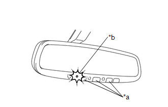
1. INSPECT GARAGE DOOR OPENER
|
(a) Press each switch and check that the red LED turns on. If one or
more of the switches does not turn on the LED, confirm normal operation
of the fuse and wire harness. If the fuse and wire harness are malfunctioning,
replace them. If not, replace the garage door opener (inner rear view mirror
assembly) (See page
|
|
.gif)
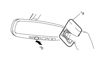
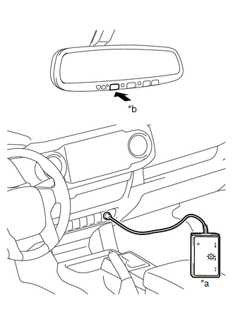
2. INSPECT GARAGE DOOR OPENER REGISTRATION AND TRANSMITTING
HINT:
Use the "HomeLink" tester and a tester transmitter for this test. First erase the customer's transmitter code, and then register the tester transmitter code.
|
(a) Check if the test transmitter code was successfully registered. Text in Illustration
HINT: If the code cannot be registered, replace the garage door opener (inner
rear view mirror assembly) (See page |
|
|
(b) Press the garage door opener switch that was registered to the tester transmitter. Check if the "HomeLink" tester's green LED illuminates. Text in Illustration
HINT: If the green LED does not illuminate, replace the garage door opener
(inner rear view mirror assembly) (See page
|
|
(c) When the inspection is complete, reregister the customer's transmitter code(s) again.
HINT:
- Registration of codes for the customer's transmitters may not be possible in the service facility if the customer's transmitters are not available or if any of the buttons are used for rolling code-type systems.
- Refer to the Owner's Manual for additional information about registration (programming) of transmitter codes.
 Registration
REGISTRATION
PROCEDURE
1. REGISTER TRANSMITTER CODE
HINT:
The vehicle's garage door opener records transmitter codes for systems
such as garage doors, gates, entry gates, door lock ...

Other materials:
Terminals Of Ecu
TERMINALS OF ECU
1. CHECK POWER WINDOW REGULATOR MASTER SWITCH ASSEMBLY
(a) for Double Cab
(1) Disconnect the P18 power window regulator master switch assembly connector.
(2) Measure the voltage and resistance according to the value(s) in the table
below.
HINT:
Measure the values on the wi ...
Side Turn Signal Light Assembly
Components
COMPONENTS
ILLUSTRATION
Removal
REMOVAL
CAUTION / NOTICE / HINT
HINT:
Use the same procedure for both the RH and LH sides.
The procedure described below is for the LH side.
PROCEDURE
1. REMOVE OUTER REAR VIEW MIRROR ASSEMBLY
(See page )
2. REMOVE OUTER ...
Fuel Pump Ecu
Components
COMPONENTS
ILLUSTRATION
Removal
REMOVAL
PROCEDURE
1. PRECAUTION
NOTICE:
After turning the ignition switch off, waiting time may be required before disconnecting
the cable from the battery terminal. Therefore, make sure to read the disconnecting
the cable from the battery ...
