Toyota Tacoma (2015-2018) Service Manual: Installation
INSTALLATION
CAUTION / NOTICE / HINT
NOTICE:
- Always use a new grommet and valve core when installing the tire pressure warning valve and transmitter.
- Check that the washer and nut are not damaged, and replace them if necessary.
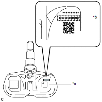
- If installing a new tire pressure warning valve and transmitter, write down the ID number before installation.
- Check that there is no oil, water or lubricant around the rim hole, tire pressure warning valve and transmitter, washer and nut. Failing to do so may result in improper installation.
- Use only a specified cap. If an unspecified cap is used, it may seize to the tire pressure warning valve and transmitter.
PROCEDURE
1. INSTALL TIRE PRESSURE WARNING VALVE AND TRANSMITTER
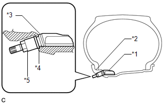
(a) Install a new grommet to the tire pressure warning valve and transmitter.
|
(b) Insert the tire pressure warning valve and transmitter into the valve installation hole. Insert it from the inside of the rim so that the printed surface can be seen. Text in Illustration
NOTICE:
|
|
|
(c) From the outside of the rim, install the washer onto the tire pressure warning valve and transmitter, and tighten the nut. Text in Illustration
Torque: 4.0 N·m {41 kgf·cm, 35 in·lbf} NOTICE:
|
|
|
(d) Set the wheel onto the mounting machine and install the lower bead. Position the main body of the tire pressure warning valve and transmitter in the shaded area shown in the illustration. Text in Illustration
NOTICE:
|
|
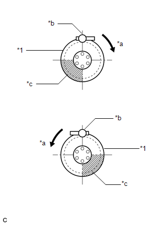
(e) Install the upper bead.
NOTICE:
Make sure that the tire bead and tool do not interfere with the main body of the tire pressure warning valve and transmitter and that it is not clamped by the bead.
(f) Install a new valve core.
(g) After the tire is inflated, the valve nut may be loose. Retighten the nut to the specified torque.
Torque:
4.0 N·m {41 kgf·cm, 35 in·lbf}
NOTICE:
No further tightening is required once the nut is tightened to the specified torque.
(h) Check for air leaks with soapy water. If there is air leakage, push the valve core 2 or 3 times to remove any dirt attached to the valve core. If air continues to leak, replace the grommet, washer and nut.
(i) Install the cap.
2. INSTALL FRONT WHEEL
Torque:
113 N·m {1152 kgf·cm, 83 ft·lbf}
3. INSTALL REAR WHEEL
Torque:
113 N·m {1152 kgf·cm, 83 ft·lbf}
4. INSPECT TIRES
.gif)
5. REGISTER TRANSMITTER ID
(See page )
6. PERFORM INITIALIZATION
(See page )
7. INSPECT TIRE PRESSURE WARNING SYSTEM
(See page )
 Disposal
DISPOSAL
CAUTION / NOTICE / HINT
HINT:
The tire pressure warning valve and transmitter is powered by a lithium battery.
When disposing of the tire pressure warning valve and transmitter, remove t ...
 Removal
REMOVAL
PROCEDURE
1. REMOVE FRONT WHEEL
2. REMOVE REAR WHEEL
3. REMOVE TIRE PRESSURE WARNING VALVE AND TRANSMITTER
(a) Remove the cap and valve core to release the air from the tire.
NOTICE:
Ke ...
Other materials:
How To Proceed With Troubleshooting
CAUTION / NOTICE / HINT
HINT:
Use these procedures to troubleshoot the smart key system (for Entry
Function).
*: Use the Techstream.
PROCEDURE
1.
VEHICLE BROUGHT TO WORKSHOP
NEXT
...
Vehicle Speed Sensor (C1A45)
DESCRIPTION
The blind spot monitor sensor receives vehicle speed signals from the skid control
ECU (brake actuator assembly) via CAN communication.
DTC Code
DTC Detection Condition
Trouble Area
C1A45
A fail flag is transmitted from the ...
Diagnostic Trouble Code Chart
DIAGNOSTIC TROUBLE CODE CHART
Main Body ECU (Multiplex Network Body ECU)
DTC Code
Detection Item
See page
B1206
P/W Master Switch Communication Stop
B1273
Sliding Roof ECU Communication Stop
...
