Toyota Tacoma (2015-2018) Service Manual: Removal
REMOVAL
PROCEDURE
1. REMOVE FRONT WHEEL
2. REMOVE REAR WHEEL
3. REMOVE TIRE PRESSURE WARNING VALVE AND TRANSMITTER
(a) Remove the cap and valve core to release the air from the tire.
NOTICE:
Keep the removed cap and valve core.
(b) After ensuring that a sufficient amount of air has been released, remove the nut and washer used to secure the tire pressure warning valve and transmitter. Drop the tire pressure warning valve and transmitter with the grommet into the tire.
HINT:
The grommet may remain attached to the rim.
|
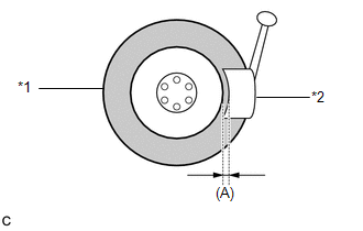
(c) After dropping the tire pressure warning valve and transmitter into the tire, disengage the bead using the shoe of a tire remover. Text in Illustration
NOTICE:
NOTICE: Be careful as the tire pressure warning valve and transmitter may become damaged due to interference between the sensor and tire bead. |
|
(d) Separate the upper bead.
(e) Take out the tire pressure warning valve and transmitter with the grommet from the tire and separate the lower bead.
(f) Remove the grommet from the tire pressure warning valve and transmitter.
 Installation
INSTALLATION
CAUTION / NOTICE / HINT
NOTICE:
Always use a new grommet and valve core when installing the tire pressure
warning valve and transmitter.
Check that the washer and nut a ...
 Vf2cm Transfer
...
Other materials:
Fuel Pressure Sensor
Components
COMPONENTS
ILLUSTRATION
Inspection
INSPECTION
PROCEDURE
1. INSPECT FUEL DELIVERY PIPE SUB-ASSEMBLY (FUEL PRESSURE SENSOR)
NOTICE:
Do not remove the fuel pressure sensor from the fuel delivery pipe sub-assembly.
If a fuel pressure sensor is removed, replace the ...
Automatic High Beam System (B124B)
DESCRIPTION
The main body ECU (multiplex network body ECU) determines the status of the automatic
high beam system based on the automatic high beam system signal from the forward
recognition camera.
DTC No.
Detection Item
DTC Detection Condition
Trou ...
Data List / Active Test
DATA LIST / ACTIVE TEST
1. DATA LIST
HINT:
Using the Techstream to read the Data List allows the values or states of switches,
sensors, actuators and other items to be read without removing any parts. This non-intrusive
inspection can be very useful because intermittent conditions or signals ...
