Toyota Tacoma (2015-2018) Service Manual: Installation
INSTALLATION
CAUTION / NOTICE / HINT
HINT:
- Use the same procedure for the RH side and LH side.
- The procedure listed below is for the LH side.
PROCEDURE
1. INSTALL FRONT COIL SPRING
|
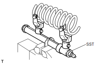
(a) Install SST to the front coil spring, and secure SST in a vise. SST: 09727-00060 SST: 09727-30021 09727-00010 09727-00031 |
|
|
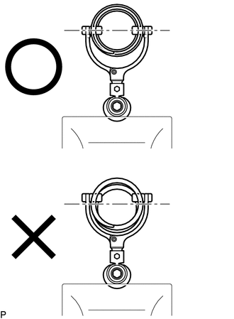
(b) Attach the arm of SST to the diameter of the front coil spring. CAUTION:
|
|
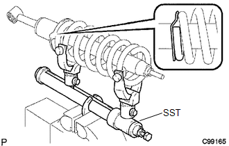
(c) Using SST, compress the front coil spring.
CAUTION:
- If the front coil spring bends during the compression, immediately stop the compression and reinstall SST.
- Do not compress the spring until the coil springs contact each other.
- Do not use an impact wrench. It will damage SST.
|
(d) Install the front coil spring to the front shock absorber assembly. HINT: Fit the lower end of the front coil spring into the gap of the spring lower seat. |
|
2. INSTALL FRONT SHOCK ABSORBER CUSHION RETAINER
3. INSTALL FRONT SUSPENSION SUPPORT SUB-ASSEMBLY
4. INSTALL FRONT SHOCK ABSORBER NO. 1 CUSHION
5. INSTALL FRONT SHOCK ABSORBER CUSHION RETAINER
6. INSTALL FRONT SUPPORT TO FRONT SHOCK ABSORBER NUT
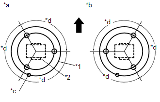
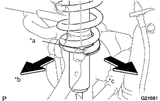
(a) Align the front suspension support sub-assembly and the front shock absorber bush as shown in the illustration.
 Text in Illustration
|
*1 |
Front Suspension Support Sub-assembly |
|
*2 |
Front Shock Absorber Bush |
|
*a |
LH Side |
|
*b |
RH Side |
|
*c |
Lower End of the Front Coil Spring |
|
*d |
120° |
.png) |
Front of the Vehicle |
(b) Fit and tighten a new front support to front shock absorber nut.
Torque:
27 N·m {275 kgf·cm, 20 ft·lbf}
CAUTION:
Do not use an impact wrench. It will damage the shock absorber rod.
(c) Release the front coil spring while checking the position of the front suspension support sub-assembly.
7. TEMPORARILY TIGHTEN FRONT SHOCK ABSORBER WITH COIL SPRING
|
(a) Install the front coil spring to the vehicle body with the lower end of the coil spring facing the rear side of the vehicle. Text in Illustration
|
|
(b) Install the 3 nuts onto the upper side of the front shock absorber with coil spring.
Torque:
64 N·m {653 kgf·cm, 47 ft·lbf}
(c) Temporarily tighten the bolt, nut and the washer on the lower side of the front shock absorber with coil spring.
8. INSTALL TIE ROD END SUB-ASSEMBLY
.gif)
9. INSTALL FRONT STABILIZER BAR
10. INSTALL FRONT NO. 1 STABILIZER BRACKET LH
11. INSTALL FRONT NO. 1 STABILIZER BRACKET RH
HINT:
Use the same procedure for the RH side and LH side.
12. INSTALL FRONT STABILIZER LINK ASSEMBLY LH
(a) Install the front stabilizer link assembly LH to the steering knuckle with the nut.
Torque:
70 N·m {714 kgf·cm, 52 ft·lbf}
HINT:
If the ball joint turns together with the nut, use a socket hexagon wrench 6 mm to hold the stud.
13. INSTALL FRONT STABILIZER LINK ASSEMBLY RH
HINT:
Use the same procedure for the RH side and LH side.
14. INSTALL NO. 1 ENGINE UNDER COVER SUB-ASSEMBLY
Torque:
30 N·m {306 kgf·cm, 22 ft·lbf}
15. INSTALL FRONT WHEEL
Torque:
113 N·m {1152 kgf·cm, 83 ft·lbf}
16. STABILIZE SUSPENSION
(a) Lower the vehicle.
(b) Bounce the vehicle up and down several times to stabilize the suspension.
17. FULLY TIGHTEN FRONT SHOCK ABSORBER WITH COIL SPRING
(a) Fully tighten the nut on the lower side of the front shock absorber with coil spring.
Torque:
83 N·m {846 kgf·cm, 61 ft·lbf}
18. INSPECT AND ADJUST FRONT WHEEL ALIGNMENT
(See page )
 Disposal
DISPOSAL
PROCEDURE
1. DISPOSE OF FRONT SHOCK ABSORBER ASSEMBLY
(a) Fully extend the shock absorber piston rod, and fix it at an angle in a vise
or similar tool.
(b) Using a drill or similar to ...
 Front Stabilizer Bar
Components
COMPONENTS
ILLUSTRATION
Inspection
INSPECTION
PROCEDURE
1. INSPECT FRONT STABILIZER LINK ASSEMBLY
(a) Flip the ball joint stud back and forth 5 times, as shown in the illustr ...
Other materials:
Installation
INSTALLATION
CAUTION / NOTICE / HINT
HINT:
Use the same procedure for both the LH and RH sides.
The procedure described below is for the LH side.
PROCEDURE
1. INSTALL HEADLIGHT ASSEMBLY
(a) Connect the connectors.
(b) Engage the clamp to install the headlight assembly.
(c) ...
Front Radar Sensor Beam Axis Not Adjusted (C1A14)
DESCRIPTION
After installing a new millimeter wave radar sensor assembly, if sensor beam
axis adjustment has not been performed, DTC C1A14 will be stored.
DTC No.
Detection Item
DTC Detection Condition
Trouble Area
C1A14
Fro ...
Cargo Light Switch
Components
COMPONENTS
ILLUSTRATION
Inspection
INSPECTION
PROCEDURE
1. INSPECT DECK LIGHT SWITCH ASSEMBLY
(a) Check the resistance.
(1) Measure the resistance according to the value(s) in the table below.
Text in Illustration
*a
Compone ...
