Toyota Tacoma (2015-2018) Service Manual: Skid Control Buzzer Circuit (C1AA7)
DESCRIPTION
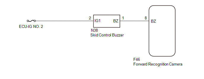
The forward recognition camera operates the pre-collision warning by sending a buzzer request signal to the skid control buzzer.
If the forward recognition camera detects a malfunction in the skid control buzzer circuit, it will output DTC C1AA7.
|
DTC No. |
Detection Item |
DTC Detection Condition |
Trouble Area |
|---|---|---|---|
|
C1AA7 |
Skid Control Buzzer Circuit |
When the ignition switch is turned to ON and the pre-collision warning is operating, and one of the following conditions is met (1 trip detection logic*):
|
|
- *: Only output while a malfunction is present.
|
Vehicle Condition |
||||
|---|---|---|---|---|
|
Pattern 1 |
Pattern 2 |
Pattern 3 |
||
|
Diagnosis Condition |
When the ignition switch is turned to ON and the pre-collision warning is operating |
â—‹ |
â—‹ |
â—‹ |
|
Malfunction Status |
A buzzer request signal is sent to the skid control buzzer but the buzzer does not sound |
â—‹ |
- |
- |
|
A buzzer request signal is not sent to the skid control buzzer but the buzzer sounds |
- |
â—‹ |
- |
|
|
There is no buzzer sounding request and an open circuit is detected in the skid control buzzer |
- |
- |
â—‹ |
|
|
Detection Time |
1 second or more |
1 second or more |
1 second or more |
|
|
Number of Trips |
1 trip |
1 trip |
1 trip |
|
HINT:
DTC will be output when conditions for either of the patterns in the table above are met.
WIRING DIAGRAM
CAUTION / NOTICE / HINT
NOTICE:
- Inspect the fuses for circuits related to this system before performing the following procedure.
- When replacing the forward recognition camera, always replace it with a new one. If a forward recognition camera which was installed to another vehicle is used, the information stored in the forward recognition camera will not match the information from the vehicle. As a result, a DTC may be stored.
- If the forward recognition camera has been replaced with a new one,
be sure to perform Forward Recognition Camera Axis Adjustment.
Click here
.gif)
PROCEDURE
|
1. |
CHECK FOR DTCs (FORWARD RECOGNITION CAMERA SYSTEM) |
(a) Clear the DTCs.
Click here
(b) Perform the Active Test according to the display on the Techstream.
Click here
NOTICE:
Perform the Active Test for 1 second or more.
HINT:
Performing the Active Test for 1 second or more causes DTC C1AA7 to be stored if the DTC detection conditions are met.
|
Tester Display |
Measurement Item |
Control Range |
Diagnostic Note |
|---|---|---|---|
|
PCS Buzzer |
Skid control buzzer |
ON / OFF |
Test possible with ignition switch ON, vehicle stopped |
(c) Check for DTCs.
Click here
|
Result |
Proceed to |
|---|---|
|
DTC C1AA7 is not output |
A |
|
DTC C1AA7 is output |
B |
| A | .gif) |
USE SIMULATION METHOD TO CHECK |
|
.gif)
|
2. |
CHECK TERMINAL VOLTAGE |
|
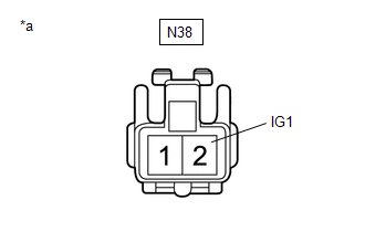
(a) Disconnect the skid control buzzer connector. |
|
(b) Measure the voltage according to the value(s) in the table below.
Standard Voltage:
|
Tester Connection |
Switch Condition |
Specified Condition |
|---|---|---|
|
N38-2 (IG1) - Body ground |
Ignition switch ON |
11 to 14 V |
|
Ignition switch off |
Below 1 V |
(c) Connect the skid control buzzer connector.
| NG | |
REPAIR OR REPLACE HARNESS OR CONNECTOR (SKID CONTROL BUZZER - BATTERY) |
|
|
3. |
CHECK HARNESS AND CONNECTOR (SKID CONTROL BUZZER - FORWARD RECOGNITION CAMERA) |
(a) Disconnect the N38 skid control buzzer connector.
(b) Disconnect the F46 forward recognition camera connector.
(c) Measure the resistance according to the value(s) in the table below.
Standard Resistance:
|
Tester Connection |
Condition |
Specified Condition |
|---|---|---|
|
N38-1 (BZ) - F46-8 (BZ) |
Always |
Below 1 Ω |
|
N38-1 (BZ) or F46-8 (BZ) - Body ground |
Always |
10 kΩ or higher |
(d) Connect the F46 forward recognition camera connector.
(e) Connect the N38 skid control buzzer connector.
| OK | |
GO TO STEP 6 |
|
|
4. |
REPAIR OR REPLACE HARNESS OR CONNECTOR (SKID CONTROL BUZZER - FORWARD RECOGNITION CAMERA) |
(a) Repair or replace the harness or connector.
|
|
5. |
CHECK FOR DTCs (FORWARD RECOGNITION CAMERA SYSTEM) |
(a) Clear the DTCs.
Click here
(b) Perform the Active Test according to the display on the Techstream.
Click here
NOTICE:
Perform the Active Test for 1 second or more.
HINT:
Performing the Active Test for 1 second or more causes DTC C1AA7 to be stored if the DTC detection conditions are met.
|
Tester Display |
Measurement Item |
Control Range |
Diagnostic Note |
|---|---|---|---|
|
PCS Buzzer |
Skid control buzzer |
ON / OFF |
Test possible with ignition switch ON, vehicle stopped |
(c) Check for DTCs.
Click here
|
Result |
Proceed to |
|---|---|
|
DTC C1AA7 is not output |
A |
|
DTC C1AA7 is output |
B |
| A | |
END |
|
|
6. |
INSPECT SKID CONTROL BUZZER (CONFIRM BUZZER OPERATION) |
(a) Turn the ignition switch to ON.
(b) Check if the skid control buzzer is sounding.
|
Result |
Proceed to |
|---|---|
|
The skid control buzzer does not sound when the ignition switch is turned to ON |
A |
|
The skid control buzzer sounds continuously when the ignition switch is turned to ON |
B |
| B | |
GO TO STEP 8 |
|
|
7. |
INSPECT SKID CONTROL BUZZER (UNIT INSPECTION) |
(a) Remove the skid control buzzer.
Click here
(b) Inspect the skid control buzzer.
Click here
|
Result |
Proceed to |
|---|---|
|
Skid control buzzer is abnormal |
A |
|
Skid control buzzer is normal |
B |
| B | |
GO TO STEP 9 |
|
|
8. |
REPLACE SKID CONTROL BUZZER |
(a) Replace the skid control buzzer.
Click here
|
|
9. |
CHECK FOR DTCs (FORWARD RECOGNITION CAMERA SYSTEM) |
(a) Clear the DTCs.
Click here
(b) Perform the Active Test according to the display on the Techstream.
Click here
NOTICE:
Perform the Active Test for 1 second or more.
HINT:
Performing the Active Test for 1 second or more causes DTC C1AA7 to be stored if the DTC detection conditions are met.
|
Tester Display |
Measurement Item |
Control Range |
Diagnostic Note |
|---|---|---|---|
|
PCS Buzzer |
Skid control buzzer |
ON / OFF |
Test possible with ignition switch ON, vehicle stopped |
(c) Check for DTCs.
Click here
|
Result |
Proceed to |
|---|---|
|
DTC C1AA7 is not output |
A |
|
DTC C1AA7 is output |
B |
| A | |
END |
| B | |
REPLACE FORWARD RECOGNITION CAMERA |
 Vehicle Speed Sensor Circuit (C1AA3)
DESCRIPTION
The forward recognition camera receives vehicle speed signals from the skid control
ECU. If the skid control ECU receives a vehicle speed sensor malfunction signal,
it informs the for ...
 FCM Destination Information Unmatched (C1AA1)
DESCRIPTION
When the forward recognition camera is replaced with a new one, the new forward
recognition camera attempts to store country specification information received
from the main body ECU ...
Other materials:
Key Reminder Buzzer does not Sound
DESCRIPTION
The key reminder warning buzzer sounds when the driver side door is opened while
the ignition switch is in the LOCK or ACC positions. The key reminder warning buzzer
is activated when the main body ECU (multiplex network body ECU) sends a key switch
signal and driver side courtesy ...
Removal
REMOVAL
CAUTION / NOTICE / HINT
HINT:
Use the same procedure for the RH and LH sides.
The procedure described below is for the LH side.
PROCEDURE
1. REMOVE FRONT DOOR GLASS RUN
2. REMOVE FRONT DOOR GLASS OUTER WEATHERSTRIP ASSEMBLY
(See page
)
3. REMOVE NO. 1 BLAC ...
System Description
SYSTEM DESCRIPTION
1. FUNCTION OF MAIN COMPONENTS
Component
Function
Vertical mirror motor
Moves the mirror surface vertically in accordance with the vertical mirror
motor outer mirror switch assembly operation.
Horizontal mirr ...
