Toyota Tacoma (2015-2018) Service Manual: Removal
REMOVAL
PROCEDURE
1. PRECAUTION
NOTICE:
After turning the ignition switch off, waiting time may be required before disconnecting the cable from the negative (-) battery terminal. Therefore, make sure to read the disconnecting the cable from the negative (-) battery terminal notices before proceeding with work.
Click here .gif)
2. RECOVER REFRIGERANT FROM REFRIGERATION SYSTEM
Click here
3. DISCONNECT CABLE FROM NEGATIVE BATTERY TERMINAL
NOTICE:
When disconnecting the cable, some systems need to be initialized after the cable is reconnected.
Click here
4. REMOVE RADIATOR ASSEMBLY (for 2TR-FE)
Click here
5. REMOVE RADIATOR ASSEMBLY (for 2GR-FKS)
Click here
6. DISCONNECT DISCHARGE HOSE SUB-ASSEMBLY
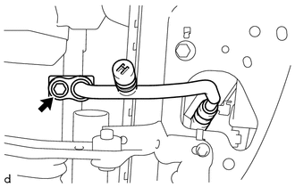
(a) Remove the bolt to disconnect the discharge hose sub-assembly from the cooler condenser assembly.
(b) Remove the O-ring from the discharge hose sub-assembly.
NOTICE:
Seal the openings of the disconnected parts using vinyl tape to prevent moisture and foreign matter from entering.
7. DISCONNECT AIR CONDITIONING TUBE ASSEMBLY
|
(a) Remove the bolt to disconnect the air conditioning tube assembly from the cooler condenser assembly. |
|
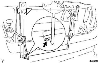
(b) Remove the O-ring from the air conditioning tube assembly.
NOTICE:
Seal the openings of the disconnected parts using vinyl tape to prevent moisture and foreign matter from entering.
8. REMOVE COOLER CONDENSER ASSEMBLY
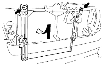
(a) Remove the 2 bolts.
(b) Lift the cooler condenser assembly up, disengage the fitting of the condenser lower bracket to remove the cooler condenser assembly from the rear side of the vehicle.
|
(c) Disengage the 2 claws to remove the 2 condenser upper brackets. |
|
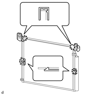
(d) Disengage the 2 claws to remove the 2 condenser lower brackets.
(e) Remove the cooler condenser assembly.
HINT:
At the time of installation, please refer to the following instructions. If installing a new condenser, add compressor oil to the condenser.
Compressor oil:
PSD1 or equivalent
Add 40 cc (1.4 fl.oz.)
 On-vehicle Inspection
ON-VEHICLE INSPECTION
PROCEDURE
1. INSPECT COOLER CONDENSER ASSEMBLY
(a) If the fins of the cooler condenser assembly are dirty, clean them with water
and dry them with compressed air.
NOTICE:
...
 Installation
INSTALLATION
PROCEDURE
1. INSTALL COOLER CONDENSER ASSEMBLY
(a) Engage the 2 claws to install the 2 condenser upper brackets.
(b) Engage the 2 claws to install the 2 condenser lower brackets.
...
Other materials:
How To Proceed With Troubleshooting
CAUTION / NOTICE / HINT
HINT:
Use the following procedure listed to troubleshoot the touch select
2-4 and high-low system.
*: Use the Techstream.
PROCEDURE
1.
VEHICLE BROUGHT TO WORKSHOP
NEXT
...
Reassembly
REASSEMBLY
PROCEDURE
1. INSTALL NO. 2 ANTENNA CORD SUB-ASSEMBLY
(a) Using hot-melt glue, install the No. 2 antenna cord sub-assembly as shown
in the illustration.
2. INSTALL NO. 1 ROOF WIRE (w/ Vanity Light)
(a) w/ EC Mirror:
(1) Align the aiming tape as shown in the illustration.
...
Interior
*1: If equipped
* 2: Access Cab and Double Cab models
*3: Vehicles with auto anti- glare inside rear view mirror
*1: If equipped
*2: Vehicles with an automatic transmission
* : If equipped
* 1: If equipped
* 2: Vehicles with sub woofer ...
