Toyota Tacoma (2015-2018) Service Manual: Installation
INSTALLATION
PROCEDURE
1. INSTALL PROPELLER SHAFT WITH CENTER BEARING ASSEMBLY
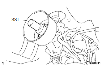
(a) Remove SST from the extension housing.
(b) Install the propeller shaft to the extension housing.
(c) Completely remove any oil or the like and clean the contact surfaces of the propeller shaft flange and differential flange.
|
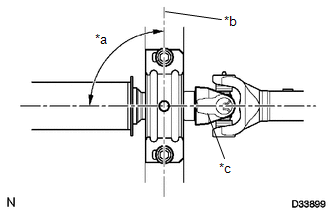
(d) Align the matchmarks on the propeller shaft flange and differential flange. Text in Illustration
|
|
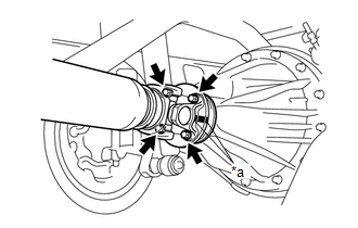
(e) for Differential Type BD20:
(1) Install the propeller shaft with the 4 bolts, 4 washers and 4 nuts.
Torque:
88 N·m {899 kgf·cm, 65 ft·lbf}
(f) for Differential Type BD22:
(1) Install the propeller shaft with the 4 washers and 4 nuts.
Torque:
88 N·m {899 kgf·cm, 65 ft·lbf}
|
(g) Temporarily install the center No. 2 support bearing assembly with the 2 bolts. Text in Illustration
HINT: Make sure the bearing is installed with the drain hole facing downwards. |
|
|
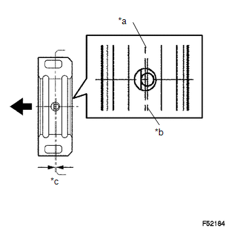
(h) Adjust the center No. 2 support bearing assembly. Text in Illustration
HINT:
|
|
(i) Tighten the 2 bolts.
Torque:
36 N·m {369 kgf·cm, 27 ft·lbf}
2. INSPECT FOR TRANSMISSION OIL LEAK
 Inspection
INSPECTION
PROCEDURE
1. INSPECT PROPELLER SHAFT WITH CENTER BEARING ASSEMBLY
(a) Using a dial indicator, check the propeller shaft with center bearing assembly
runout.
Maximum runout:
0.6 mm ...
 Reassembly
REASSEMBLY
PROCEDURE
1. INSPECT CENTER NO. 2 SUPPORT BEARING ASSEMBLY
(a) When turning the center No. 2 support bearing assembly with your hand, check
that it turns smoothly without catching an ...
Other materials:
Parking Brake Cable
Components
COMPONENTS
ILLUSTRATION
Removal
REMOVAL
PROCEDURE
1. DISCONNECT NO. 2 PARKING BRAKE SHOE ASSEMBLY WITH PARKING BRAKE SHOE LEVER
(See page )
2. REMOVE VOLTAGE INVERTER ASSEMBLY
(See page )
3. REMOVE NO. 2 PARKING BRAKE CABLE ASSEMBLY
(a) Loosen the adjusting n ...
Reassembly
REASSEMBLY
PROCEDURE
1. INSPECT CENTER NO. 2 SUPPORT BEARING ASSEMBLY
(a) Turn the center bearing by hand, check that it turns smoothly without catching
and that there are no cracks or damage.
If there are any defects, replace it.
2. INSTALL CENTER NO. 2 SUPPORT BEARING ASSEMBLY
(a) Instal ...
Removal
REMOVAL
CAUTION / NOTICE / HINT
HINT:
When removing the name plates or stripe tapes, heat the vehicle body or tail
gate and name plates or stripe tapes using a heat light.
Heating Temperature
Item
Temperature
Vehicle Body or Tail Gate
40 to 60 ...
