Toyota Tacoma (2015-2018) Service Manual: Removal
REMOVAL
PROCEDURE
1. REMOVE FRONT DOOR SCUFF PLATE LH (for Double Cab)
.gif)
2. REMOVE FRONT DOOR SCUFF PLATE LH (for Access Cab)
3. REMOVE COWL SIDE TRIM BOARD LH
4. REMOVE INSTRUMENT CLUSTER CENTER FINISH PANEL SUB-ASSEMBLY
5. REMOVE INSTRUMENT CLUSTER FINISH PANEL ASSEMBLY
6. REMOVE INSTRUMENT PANEL LOWER FINISH PANEL SUB-ASSEMBLY
7. REMOVE NAVIGATION RECEIVER ASSEMBLY WITH BRACKET (w/ Navigation System)
8. REMOVE RADIO AND DISPLAY RECEIVER ASSEMBLY WITH BRACKET (w/o Navigation System)
9. REMOVE HAZARD WARNING SIGNAL SWITCH ASSEMBLY (AIR CONDITIONING CONTROL ASSEMBLY) (for Automatic Air Conditioning System)
|
(a) Disengage the 8 clips to separate the hazard warning signal switch assembly (air conditioning control assembly). |
|
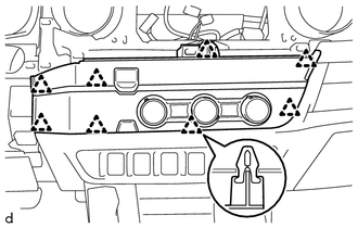
(b) Disconnect the connectors to remove the hazard warning signal switch assembly (air conditioning control assembly).
10. REMOVE HAZARD WARNING SIGNAL SWITCH ASSEMBLY (AIR CONDITIONING CONTROL ASSEMBLY) (for Manual Air Conditioning System)
|
(a) Disengage the 8 clips to separate the hazard warning signal switch assembly (air conditioning control assembly). |
|
(b) Disconnect the connectors to remove the hazard warning signal switch assembly (air conditioning control assembly).
 Components
COMPONENTS
ILLUSTRATION
ILLUSTRATION
...
 Inspection
INSPECTION
PROCEDURE
1. INSPECT HAZARD WARNING SIGNAL SWITCH ASSEMBLY (AIR CONDITIONING CONTROL ASSEMBLY)
(a) Check the resistance.
(1) Measure the resistance according to the value(s) ...
Other materials:
Downhill Assist Control Switch Malfunction (Test Mode DTC) (C1379)
DESCRIPTION
DTC C1379 is cleared when the crawl control switch sends a crawl control operation
signal or when test mode ends.
DTC Code
DTC Detection Condition
Trouble Area
C1379
Stored only during test mode.
Crawl ...
Heater Relay
Inspection
INSPECTION
PROCEDURE
1. INSPECT HEATER RELAY
(a) Check the resistance.
(1) Using an ohmmeter, measure the resistance between each terminal.
Standard:
Tester Connection
Specified Condition
3 - 4
...
No Response from Steering Lock ECU (B2786)
DESCRIPTION
This DTC is stored when LIN communication between the certification ECU (smart
key ECU assembly) and steering lock ECU (steering lock actuator or upper bracket
assembly) stops for 10 seconds or more.
DTC No.
DTC Detection Condition
Trouble Area
...
