Toyota Tacoma (2015-2018) Service Manual: Reassembly
REASSEMBLY
PROCEDURE
1. INSPECT CENTER NO. 2 SUPPORT BEARING ASSEMBLY
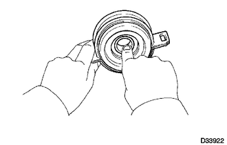
(a) When turning the center No. 2 support bearing assembly with your hand, check that it turns smoothly without catching and that there are no cracks or damage.
If there are any defects, replace it.
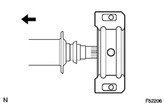
2. INSTALL CENTER NO. 2 SUPPORT BEARING ASSEMBLY
(a) Install the center No. 2 support bearing assembly to the propeller shaft with center bearing assembly.
 Text in Illustration
.png) |
Front |
(b) Coat the splines of the propeller shaft with center bearing assembly with MP grease.
(c) Install the 2 washers.
|
(d) Align the matchmarks on the universal joint yoke and propeller shaft with center bearing assembly. Text in Illustration
HINT: If replacing either the universal joint yoke or propeller shaft with center bearing assembly, assemble them so that the front side yoke of the propeller shaft with center bearing assembly and the universal joint yoke are facing in the same direction. |
|
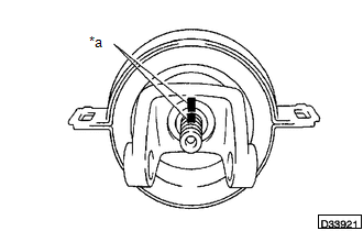
(e) Install the plate washer.
(f) Clamp the universal joint yoke in a vise, and press the bearing into position by tightening a new nut.
Torque:
200 N·m {2038 kgf·cm, 148 ft·lbf}
(g) Using a chisel and hammer, stake the lock nut.
3. INSTALL PROPELLER SHAFT UNIVERSAL JOINT SPIDER BEARING
.png)
(a) Apply MP grease to a new spider and bearings.
(b) Fit the spider into the flange yoke.
|
(c) Measure dimension A between the snap ring grooves. |
|
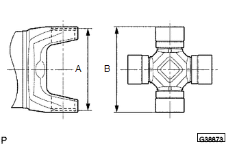
(d) Insert the spider bearing into the spider journal portion, and then measure dimension B of the universal joint.
NOTICE:
When measuring dimension B, fix the spider and spider bearings in a vise and hold them firmly together.
|
(e) Select snap rings to make dimensions A and B the same. Snap Ring Type:
NOTICE:
|
|
.png)
|
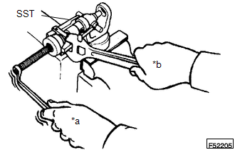
(f) Insert the spider into the yoke, and then using SST, press the spider bearing into the snap ring groove. Text in Illustration
SST: 09332-25010 |
|
(g) Press in the spider bearing on the opposite side in the same way.
NOTICE:
When pressing in the spider bearing, be careful not to damage its lip.
|
(h) Using needle-nose pliers, install 4 new snap rings into the grooves of the yoke. |
|
.png)
4. INSPECT PROPELLER SHAFT UNIVERSAL JOINT SPIDER BEARING
(a) Check the spider bearings for wear and damage.
(b) Check each spider bearing's axial play by turning the yoke while holding the shaft tightly.
Maximum bearing axial play:
0 to 0.05 mm (0 to 0.00197 in.)
 Installation
INSTALLATION
PROCEDURE
1. INSTALL PROPELLER SHAFT WITH CENTER BEARING ASSEMBLY
(a) Remove SST from the extension housing.
(b) Install the propeller shaft to the extension housing.
(c) Completel ...

Other materials:
Reassembly
REASSEMBLY
PROCEDURE
1. INSTALL REAR BUMPER SIDE STAY LH
(a) Install the rear bumper side stay LH with the 2 bolts.
Torque:
30 N·m {306 kgf·cm, 22 ft·lbf}
2. INSTALL REAR BUMPER SIDE STAY RH
HINT:
Use the same procedure as for ...
Problem Symptoms Table
PROBLEM SYMPTOMS TABLE
HINT:
Use the table below to help determine the cause of problem symptoms.
If multiple suspected areas are listed, the potential causes of the symptoms
are listed in order of probability in the "Suspected Area" column of the
table. Check each sy ...
Four Wheel Drive (4WD) Range Signal Circuit Range / Performance (P279E)
DESCRIPTION
When the transfer position switch is switched, the 2-4 terminal and LO terminal
change to one of the following ON/OFF combinations listed in the table below.
Terminal
2WD
Between 2WD and H4
H4
Between H4 and L4
L4
...
