Toyota Tacoma (2015-2018) Service Manual: Removal
REMOVAL
PROCEDURE
1. REMOVE MILLIMETER WAVE RADAR WIRE
|
(a) for Type A: (1) Disconnect the 2 connectors. (2) Using a clip remover, disengage the 4 clamps to remove the millimeter wave radar wire. |
|
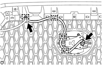
|
(b) for Type B: (1) Disconnect the 2 connectors. (2) Using a clip remover, disengage the 4 clamps to remove the millimeter wave radar wire. |
|
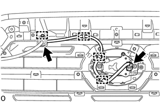
|
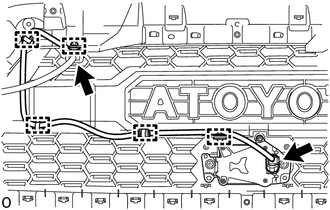
(c) for Type C: (1) Disconnect the 2 connectors. (2) Using a clip remover, disengage the 5 clamps to remove the millimeter wave radar wire. |
|
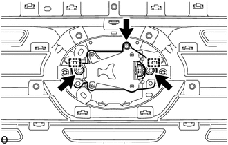
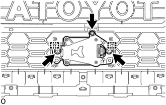
2. REMOVE MILLIMETER WAVE RADAR SENSOR ASSEMBLY
NOTICE:
Do not reuse the millimeter wave radar sensor assembly if it has been dropped or subjected to a severe impact.
|
(a) for Type A: (1) Remove the 2 bolts and screw. (2) Disengage the 2 guides to remove the millimeter wave radar sensor assembly. |
|
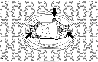
|
(b) for Type B: (1) Remove the 2 bolts and screw. (2) Disengage the 2 guides to remove the millimeter wave radar sensor assembly. |
|
|
(c) for Type C: (1) Remove the 2 bolts and screw. (2) Disengage the 2 guides to remove the millimeter wave radar sensor assembly. |
|
 Adjustment
ADJUSTMENT
CAUTION / NOTICE / HINT
CAUTION:
Radiofrequency radiation exposure information:
This equipment complies with FCC radiation exposure limits set forth
for an uncontrolled envir ...
 Installation
INSTALLATION
CAUTION / NOTICE / HINT
NOTICE:
If the millimeter wave radar sensor assembly has been struck or dropped, replace
the millimeter wave radar sensor assembly with a new one.
PROCEDURE
...
Other materials:
Removal
REMOVAL
PROCEDURE
1. REMOVE AIR CONDITIONING CONTROL ASSEMBLY (for Automatic Air Conditioning System)
Click here
2. REMOVE AIR CONDITIONING CONTROL ASSEMBLY (for Manual Air Conditioning System)
Click here
3. REMOVE LOWER NO. 2 INSTRUMENT PANEL AIRBAG ASSEMBLY
Click here
4. REMOVE INSTR ...
Components
COMPONENTS
ILLUSTRATION
*A
w/ Front Spoiler
-
-
*1
RADIATOR GRILLE
*2
FRONT NO. 1 WHEEL OPENING EXTENSION PAD
ILLUSTRATION
*A
w/o Over Fender
-
- ...
What to do if...
■ Instrument cluster
■ Center panel
■Warning lights
*1: Slip indicator comes on.
*2: The indicator flashes to indicate a malfunction.
GAS STATION INFORMATION
...
