Toyota Tacoma (2015-2018) Service Manual: Inspection
INSPECTION
PROCEDURE
1. INSPECT OIL CLEARANCE
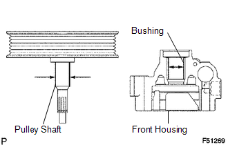
(a) Using a micrometer and caliper gauge, measure the oil seal clearance.
Standard clearance:
0.021 to 0.043 mm (0.0008 to 0.0017 in.)
Maximum clearance:
0.07 mm (0.0028 in.)
If it is greater than the maximum, replace the vane pump assembly.
2. INSPECT VANE PUMP ROTOR AND VANE PUMP PLATE
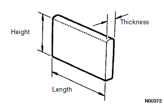
(a) Using a micrometer, measure the height, thickness and length of the vane plates.
Minimum height:
7.7 mm (0.303 in.)
Minimum thickness:
1.408 mm (0.0554 in.)
Minimum length:
11.993 mm (0.4722 in.)
|
(b) Using a feeler gauge, measure the clearance between a side face of the vane pump rotor groove and vane plate. Maximum clearance: 0.025 mm (0.0012 in.) If it is greater than the maximum, replace the vane pump assembly. |
|

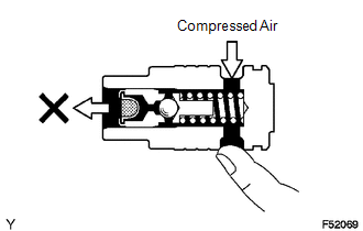
3. INSPECT FLOW CONTROL VALVE
.png)
(a) Coat the flow control valve with power steering fluid and check that it falls smoothly into the flow control valve hole under its own weight.
|
(b) Check the flow control valve for leakage. Close one of the holes and apply compressed air of 392 to 490 kPa (4 to 5 kgf/cm2, 57 to 71 psi) to the hole on the opposite side. Confirm that the air does not flow out of the end hole. If necessary, replace the vane pump assembly. |
|
4. INSPECT COMPRESSION SPRING
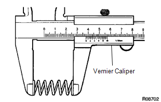
(a) Using vernier caliper, measure the free length of the spring.
Minimum free length:
36.9 mm (1.453 in.)
If it is not within the specification, replace the vane pump assembly.
5. INSPECT PRESSURE PORT UNION SUB-ASSEMBLY
(a) If the union seat in the pressure port union is badly damaged, it could cause fluid leakage, so replace the vane pump assembly.
 Removal
REMOVAL
PROCEDURE
1. PRECAUTION
NOTICE:
After turning the ignition switch off, waiting time may be required before disconnecting
the cable from the negative (-) battery terminal.
Therefore, mak ...
 Installation
INSTALLATION
PROCEDURE
1. INSTALL VANE PUMP
(a) Install the vane pump assembly with the 2 bolts.
Torque:
21 N·m {214 kgf·cm, 15 ft·lbf}
(b) Connect the oil pressure switch conne ...
Other materials:
Removal
REMOVAL
CAUTION / NOTICE / HINT
NOTICE:
Before starting the work, make sure that the ignition switch is off
and depress the brake pedal more than 20 times.
As high pressure is applied to the No. 1 brake actuator tube, never
deform it.
Do not turn the ignition switch to ON ...
Components
COMPONENTS
ILLUSTRATION
*A
w/ Off Road Package
-
-
*1
NO. 1 ENGINE UNDER COVER SUB-ASSEMBLY
*2
NO. 2 ENGINE UNDER COVER SUB-ASSEMBLY
*3
FRONT UPPER FENDER APRON SEAL
...
Disassembly
DISASSEMBLY
PROCEDURE
1. REMOVE INTAKE VALVE
(a) Using SST, compress the inner compression spring and remove the valve
spring retainer locks.
SST: 09202-70020
SST: 09202-00021
09202-01010
09202-01020
(b) Remove the valve s ...
