Toyota Tacoma (2015-2018) Service Manual: Removal
REMOVAL
PROCEDURE
1. PRECAUTION
NOTICE:
After turning the ignition switch off, waiting time may be required before disconnecting the cable from the negative (-) battery terminal.
Therefore, make sure to read the disconnecting the cable from the negative (-) battery terminal notices before proceeding with work.
Click here .gif)
2. DISCONNECT CABLE FROM NEGATIVE BATTERY TERMINAL
NOTICE:
When disconnecting the cable, some systems need to be initialized after the cable is reconnected.
Click here
3. REMOVE NO. 1 ENGINE UNDER COVER SUB-ASSEMBLY
4. REMOVE FAN AND GENERATOR V BELT
Click here
5. DRAIN POWER STEERING FLUID
6. DISCONNECT PRESSURE FEED TUBE ASSEMBLY
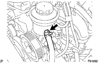
(a) Disengage the clip and disconnect the return hose.
|
(b) Remove the union bolt, then disconnect the pressure feed tube. |
|
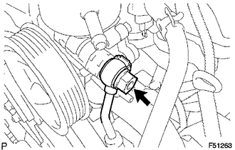
(c) Remove the gasket from the pressure feed tube.
7. REMOVE VANE PUMP
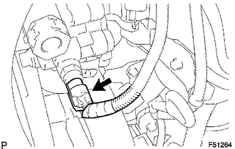
(a) Disconnect the oil pressure switch connector.
|
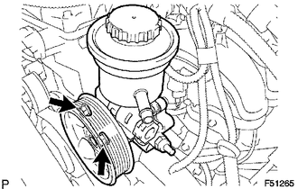
(b) Remove the 2 bolts and vane pump assembly. |
|
 Disassembly
DISASSEMBLY
PROCEDURE
1. FIX VANE PUMP
(a) Using SST, fix the vane pump assembly in a vise.
SST: 09630-00014
09631-00132
NOTICE:
When using a vise, do not overtighten it.
2. REMOVE VANE PUMP ...
 Inspection
INSPECTION
PROCEDURE
1. INSPECT OIL CLEARANCE
(a) Using a micrometer and caliper gauge, measure the oil seal clearance.
Standard clearance:
0.021 to 0.043 mm (0.0008 to 0.0017 in.)
Maximum cl ...
Other materials:
On-vehicle Inspection
ON-VEHICLE INSPECTION
PROCEDURE
1. INSPECT BRAKE PEDAL HEIGHT
(a) Check the brake pedal height.
Pedal height from dash panel:
Type
Pedal Height
Automatic transmission
164.4 to 174.4 mm (6.473 to 6.866 in.)
Manual transmission ...
Correct driving posture
Drive in a good posture as follows:
Sit upright and well back in the
seat.
Adjust the position of the seat
forward or backward to ensure the pedals can be reached and easily depressed to
the extent required.
Adjust the seatback so that the
controls are easily operable.
Adjust the t ...
Back-up Light Switch
Components
COMPONENTS
ILLUSTRATION
Inspection
INSPECTION
PROCEDURE
1. INSPECT BACK-UP LIGHT SWITCH ASSEMBLY
(a) Measure the resistance according to the value(s) in the table below.
Text in Illustration
*a
Pushed
...
