Toyota Tacoma (2015-2018) Service Manual: Inspection
INSPECTION
PROCEDURE
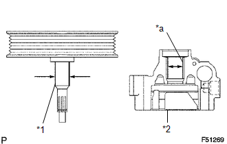
1. INSPECT OIL CLEARANCE
|
(a) Using a micrometer and caliper gauge, measure the oil seal clearance. Text in Illustration
Standard clearance: 0.021 to 0.043 mm (0.0008 to 0.0017 in.) Maximum clearance: 0.07 mm (0.0028 in.) If it is greater than the maximum, replace the vane pump assembly. |
|
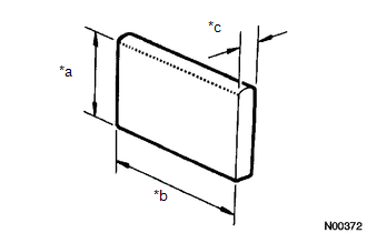
2. INSPECT VANE PUMP ROTOR AND VANE PUMP PLATE
|
(a) Using a micrometer, measure the height, thickness and length of the vane pump plates. Text in Illustration
Minimum height: 7.7 mm (0.303 in.) Minimum thickness: 1.408 mm (0.0554 in.) Minimum length: 11.993 mm (0.4722 in.) |
|
|
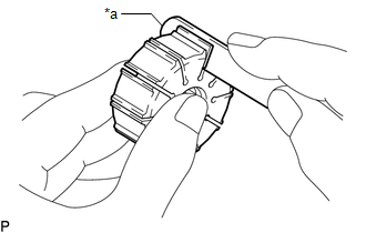
(b) Using a feeler gauge, measure the clearance between a side face of the vane pump rotor groove and vane pump plate. Text in Illustration
Maximum clearance: 0.025 mm (0.0012 in.) If it is greater than the maximum, replace the vane pump assembly. |
|
3. INSPECT FLOW CONTROL VALVE
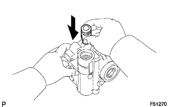
(a) Coat the flow control valve with power steering fluid and check that it falls smoothly into the flow control valve hole under its own weight.
|
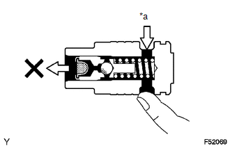
(b) Check the flow control valve for leakage. Close one of the holes and apply compressed air of 392 to 490 kPa (4.0 to 5.0 kgf/cm2, 57 to 71 psi) to the hole on the opposite side. Confirm that the air does not flow out of the end holes. Text in Illustration
If necessary, replace the vane pump assembly. |
|
4. INSPECT COMPRESSION SPRING
|
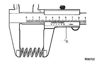
(a) Using a vernier caliper, measure the free length of the spring. Text in Illustration
Minimum free length: 36.9 mm (1.453 in.) If it is not within the specification, replace the vane pump assembly. |
|
5. INSPECT PRESSURE PORT UNION SUB-ASSEMBLY
(a) If the union seat in the pressure port union sub-assembly is badly damaged, it could cause fluid leakage, so replace the vane pump assembly.
 Removal
REMOVAL
PROCEDURE
1. REMOVE NO. 2 ENGINE UNDER COVER SUB-ASSEMBLY (w/ Off Road Package)
2. REMOVE NO. 1 ENGINE UNDER COVER SUB-ASSEMBLY
3. REMOVE FAN AND GENERATOR V BELT
4. DRAIN POWER STEERI ...
 Installation
INSTALLATION
PROCEDURE
1. INSTALL VANE PUMP ASSEMBLY
(a) Install the vane pump assembly with the 2 bolts.
Torque:
21 N·m {214 kgf·cm, 15 ft·lbf}
(b) Connect the ground wire with the bolt.
T ...
Other materials:
Hazard Warning Switch Circuit
DESCRIPTION
The combination meter assembly receives information signals from the telltale
light assembly (hazard warning signal switch).
WIRING DIAGRAM
CAUTION / NOTICE / HINT
NOTICE:
Inspect the fuses for circuits related to this system before performing the following
inspection procedur ...
Installation
INSTALLATION
CAUTION / NOTICE / HINT
CAUTION:
Some of these service operations affect the SRS airbag system. Read the precautionary
notices concerning the SRS airbag system before servicing.
Click here
PROCEDURE
1. INSTALL FRONT SEAT INNER BELT ASSEMBLY
(a) for Driver Side:
(1) Install t ...
Auxiliary boxes
Front
Pull the lid down.
Under the rear seats (Access Cab
models)
Pull up the lever.
Raise the bottom cushion up.
Turn the knob counterclockwise.
Open the lid.
Press the lid against the bottom
of the lower cushion until it is supported by the hookand- loop fastener.
Make sur ...
