Toyota Tacoma (2015-2018) Service Manual: Removal
REMOVAL
PROCEDURE
1. REMOVE NO. 2 ENGINE UNDER COVER SUB-ASSEMBLY (w/ Off Road Package)
2. REMOVE NO. 1 ENGINE UNDER COVER SUB-ASSEMBLY
3. REMOVE FAN AND GENERATOR V BELT
.gif)
4. DRAIN POWER STEERING FLUID
5. REMOVE FRONT FENDER APRON UPPER SEAL RH
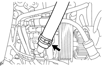
6. DISCONNECT NO. 1 OIL RESERVOIR TO PUMP HOSE
|
(a) Slide the clip and disconnect the No. 1 oil reservoir to pump hose. |
|
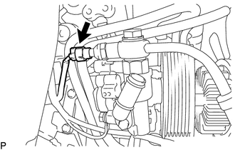
7. DISCONNECT PRESSURE FEED TUBE ASSEMBLY
|
(a) Disconnect the oil pressure switch connector. |
|
|
(b) Remove the union bolt to disconnect the pressure feed tube assembly. |
|
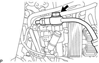
(c) Remove the gasket from the pressure feed tube assembly.
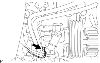
8. REMOVE VANE PUMP ASSEMBLY
|
(a) Remove the bolt to disconnect the ground wire. |
|
|
(b) Remove the 2 bolts and vane pump assembly. |
|
.png)
 Disassembly
DISASSEMBLY
PROCEDURE
1. FIX VANE PUMP ASSEMBLY
(a) Using SST, fix the vane pump assembly in a vise.
SST: 09630-00014
09631-00132
NOTICE:
When using a vise, do not overtighte ...
 Inspection
INSPECTION
PROCEDURE
1. INSPECT OIL CLEARANCE
(a) Using a micrometer and caliper gauge, measure the oil seal clearance.
Text in Illustration
*1
Pu ...
Other materials:
Precaution
PRECAUTION
1. PRECAUTIONS FOR REFRIGERANT HFO-1234yf (R1234yf)
(a) Compatibility
(1) The parts used in the refrigerant cycle, the compressor oil, etc. of the
HFO-1234yf (R1234yf) system are not compatible with the conventional HFC-134a (R134a)
system.
(b) HFO-1234yf (R1234yf) Refrigerant
(1 ...
Air Inlet Damper Control Servo Motor Circuit (B1442/42)
DESCRIPTION
This No. 1 air conditioning servo assembly (fresh/recirculation damper) is controlled
by the air conditioning amplifier assembly and moves the air inlet damper to the
desired position.
DTC No.
DTC Detection Condition
Trouble Area
B1 ...
Data List / Active Test
DATA LIST / ACTIVE TEST
1. DATA LIST
NOTICE:
In the table below, the values listed under "Normal Condition" are reference
values. Do not depend solely on these reference values when deciding whether a part
is faulty or not.
HINT:
Using the Techstream to read the Data List allows t ...
