Toyota Tacoma (2015-2018) Service Manual: Inspection
INSPECTION
PROCEDURE
1. INSPECT SHIFT SOLENOID VALVE SL1
|
(a) Measure the resistance according to the value(s) in the table below. Text in Illustration
Standard Resistance:
If the value is not as specified, replace the shift solenoid valve SL1. |
|
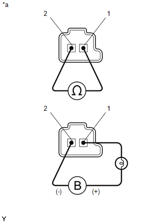
(b) Apply 12 V battery voltage to the shift solenoid valve and check that the valve moves and makes an operating noise.
OK:
|
Measurement Condition |
Specified Condition |
|---|---|
|
Valve moves and makes an operating noise |
If the operation cannot be done as specified, replace the shift solenoid valve SLT.
2. INSPECT SHIFT SOLENOID VALVE SL2
HINT:
Refer to Inspect Shift Solenoid Valve SL1.
3. INSPECT SHIFT SOLENOID VALVE SL3
HINT:
Refer to Inspect Shift Solenoid Valve SL1.
4. INSPECT SHIFT SOLENOID VALVE SL4
HINT:
Refer to Inspect Shift Solenoid Valve SL1.
5. INSPECT SHIFT SOLENOID VALVE SLU
HINT:
Refer to Inspect Shift Solenoid Valve SL1.
6. INSPECT SHIFT SOLENOID VALVE SLT
HINT:
Refer to Inspect Shift Solenoid Valve SL1.
7. INSPECT SHIFT SOLENOID VALVE SL
|
(a) Measure the resistance according to the value(s) in the table below. Text in Illustration
Standard Resistance:
If the value is not as specified, replace the shift solenoid valve SL. |
|
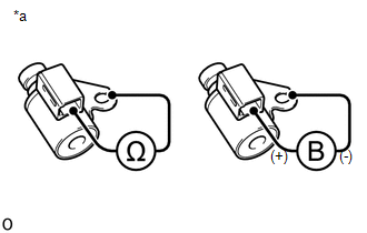
(b) Apply 12 V battery voltage to the shift solenoid valve and check that the valve moves and makes an operating noise.
OK:
|
Measurement Condition |
Specified Condition |
|---|---|
|
Valve moves and makes an operating noise |
 Removal
REMOVAL
PROCEDURE
1. DISCONNECT TRANSMISSION WIRE
(See page )
2. REMOVE VALVE BODY OIL STRAINER ASSEMBLY
(a) Remove the 3 bolts and valve body oil strainer assembly from the
trans ...
 Reassembly
REASSEMBLY
PROCEDURE
1. INSTALL SHIFT SOLENOID VALVE SLT
(a) Install the shift solenoid valve SLT and straight pin to the transmission
valve body assembly.
...
Other materials:
Data List / Active Test
DATA LIST / ACTIVE TEST
1. DATA LIST
HINT:
Using the Techstream to read the Data List allows the values or states of switches,
sensors, actuators and other items to be read without removing any parts. This non-intrusive
inspection can be very useful because intermittent conditions or signals ...
Components
COMPONENTS
ILLUSTRATION
*A
for Double Cab
*B
w/o Woofer
*C
w/ Woofer
-
-
*1
LUGGAGE COMPARTMENT SIDE TRAY RH
-
-
ILLUSTRATION
*A ...
Removal
REMOVAL
CAUTION / NOTICE / HINT
HINT:
Use the same procedure for the LH side and RH side.
The following procedure listed is for the LH side.
PROCEDURE
1. REMOVE FRONT WHEEL
2. DRAIN BRAKE FLUID
NOTICE:
Immediately wash off any brake fluid that comes into contact with any pa ...
