Toyota Tacoma (2015-2018) Service Manual: Removal
REMOVAL
PROCEDURE
1. DISCONNECT TRANSMISSION WIRE
(See page .gif) )
)
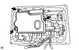
2. REMOVE VALVE BODY OIL STRAINER ASSEMBLY
|
(a) Remove the 3 bolts and valve body oil strainer assembly from the transmission valve body assembly. |
|
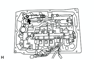
3. REMOVE TRANSMISSION VALVE BODY ASSEMBLY
|
(a) Remove the bolt, detent spring cover and detent spring from the transmission valve body assembly. |
|
|
(b) Remove the 12 bolts and transmission valve body assembly from the automatic transmission case sub-assembly. |
|

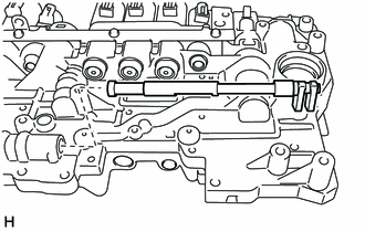
4. REMOVE MANUAL VALVE
|
(a) Remove the manual valve from the transmission valve body assembly. |
|
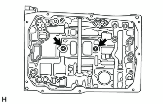
5. REMOVE TRANSMISSION CASE GASKET
|
(a) Remove the 2 transmission case gaskets from the automatic transmission case sub-assembly. |
|
 Components
COMPONENTS
ILLUSTRATION
ILLUSTRATION
...
 Inspection
INSPECTION
PROCEDURE
1. INSPECT SHIFT SOLENOID VALVE SL1
(a) Measure the resistance according to the value(s) in the table below.
Text in Illustration
*a
...
Other materials:
Maintenance requirements
To ensure safe and economical driving, day-to-day care and regular maintenance
is essential. It is the owner’s responsibility to perform regular checks. Toyota
recommends the following maintenance.
■ General maintenance
Should be performed on a daily basis. This can be done by yourself ...
Terminals Of Ecu
TERMINALS OF ECU
1. REAR TELEVISION CAMERA ASSEMBLY
(a) Disconnect the T22 television camera assembly connector.
(b) Measure the voltage and resistance according to the value(s) in the table
below.
Terminal No. (Symbol)
Wiring Color
Terminal Description
...
Removal
REMOVAL
PROCEDURE
1. PRECAUTION
NOTICE:
After turning the ignition switch off, waiting time may be required before disconnecting
the cable from the negative (-) battery terminal. Therefore, make sure to read the
disconnecting the cable from the negative (-) battery terminal notices before pr ...
