Toyota Tacoma (2015-2018) Service Manual: Reassembly
REASSEMBLY
PROCEDURE
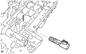
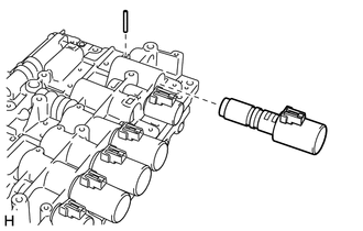
1. INSTALL SHIFT SOLENOID VALVE SLT
|
(a) Install the shift solenoid valve SLT and straight pin to the transmission valve body assembly. |
|
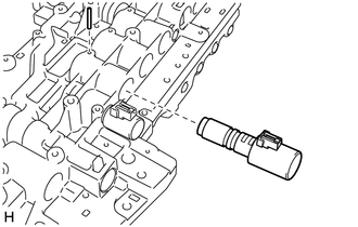
2. INSTALL SHIFT SOLENOID VALVE SL2
|
(a) Install the shift solenoid valve SL2 and straight pin to the transmission valve body assembly. |
|
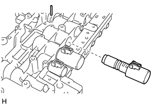
3. INSTALL SHIFT SOLENOID VALVE SL1
|
(a) Install the shift solenoid valve SL1 and straight pin to the transmission valve body assembly. |
|
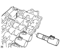
4. INSTALL SHIFT SOLENOID VALVE SL3
|
(a) Install the shift solenoid valve SL3 and straight pin to the transmission valve body assembly. |
|
5. INSTALL SHIFT SOLENOID VALVE SLU
|
(a) Install the shift solenoid valve SLU and straight pin to the transmission valve body assembly. |
|
6. INSTALL SHIFT SOLENOID VALVE SL4
|
(a) Install the shift solenoid valve SL4 and straight pin to the transmission valve body assembly. |
|
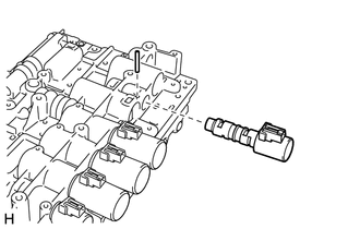
7. INSTALL SHIFT SOLENOID VALVE SL
|
(a) Install the shift solenoid valve SL and straight pin to the transmission valve body assembly. Torque: 6.4 N·m {65 kgf·cm, 57 in·lbf} |
|
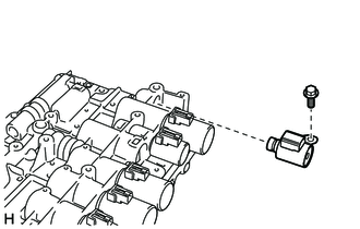
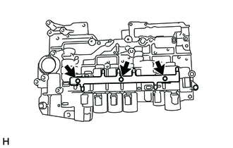
8. INSTALL SOLENOID LOCK PLATE
|
(a) Install the solenoid lock plate to the transmission valve body assembly with the 3 bolts. Torque: 6.4 N·m {65 kgf·cm, 57 in·lbf} |
|
 Inspection
INSPECTION
PROCEDURE
1. INSPECT SHIFT SOLENOID VALVE SL1
(a) Measure the resistance according to the value(s) in the table below.
Text in Illustration
*a
...
 Installation
INSTALLATION
PROCEDURE
1. INSTALL TRANSMISSION CASE GASKET
(a) Install 2 new transmission case gaskets to the automatic transmission case
sub-assembly.
2. INSTALL MANUAL VALVE
(a) Coat the manu ...
Other materials:
Seat Position Sensor
Components
COMPONENTS
ILLUSTRATION
On-vehicle Inspection
ON-VEHICLE INSPECTION
PROCEDURE
1. INSPECT SEAT POSITION AIRBAG SENSOR (for Vehicle not Involved in Collision)
(a) Perform a diagnostic system check (See page
).
2. INSPECT SEAT POSITION AIRBAG SENSOR (for Vehicle Involved in C ...
Inspection
INSPECTION
PROCEDURE
1. INSPECT FUEL INJECTOR ASSEMBLY
NOTICE:
This inspection aims at inspecting the fuel injectors for opens or shorts, because
the fuel injectors of this vehicle are a high-pressure type and cannot be inspected
for fuel injection volume.
(a) Measure the resistance accordi ...
Components
COMPONENTS
ILLUSTRATION
*A
w/ Off Road Package
-
-
*1
NO. 1 ENGINE UNDER COVER SUB-ASSEMBLY
*2
NO. 2 ENGINE UNDER COVER SUB-ASSEMBLY
*3
FRONT UPPER FENDER APRON SEAL
...
