Toyota Tacoma (2015-2018) Service Manual: Disassembly
DISASSEMBLY
PROCEDURE
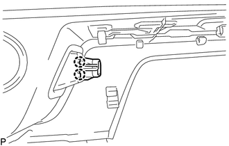
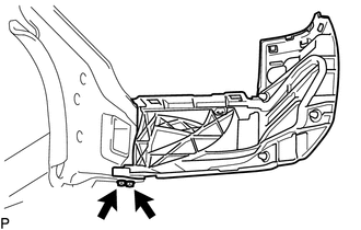
1. REMOVE CONNECTOR COVER
|
(a) Disengage the 2 clips to remove the connector cover. |
|
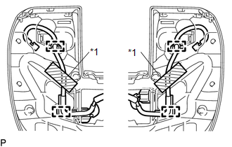
2. REMOVE REAR BUMPER PAD SUB-ASSEMBLY
|
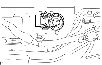
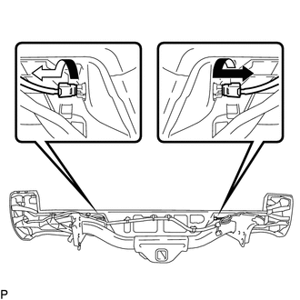
(a) Separate the 2 license plate light assemblies as shown in the illustration. |
|
|
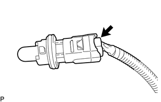
(b) Disconnect the connector to remove the license plate light socket. HINT: Use the same procedure for the RH side and LH side. |
|
(c) w/ Clearance Sonar System:
(1) Remove the 3 clips.
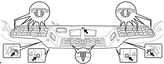
(2) Disengage the 14 claws to separate the rear bumper pad sub-assembly.
(3) Disconnect the 2 connectors to remove the rear bumper pad sub-assembly.
(d) w/o Clearance Sonar System:
(1) Remove the 3 clips.
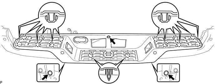
(2) Disengage the 14 claws to remove the rear bumper pad sub-assembly.
|
(e) Disengage the 2 claws to remove the license plate light lens. HINT: Use the same procedure for the RH side and LH side. |
|
3. REMOVE NO. 1 ULTRASONIC SENSOR (w/ Clearance Sonar System)
.gif)
4. REMOVE REAR BUMPER PLATE
(a) Disengage the wire harness clamps.
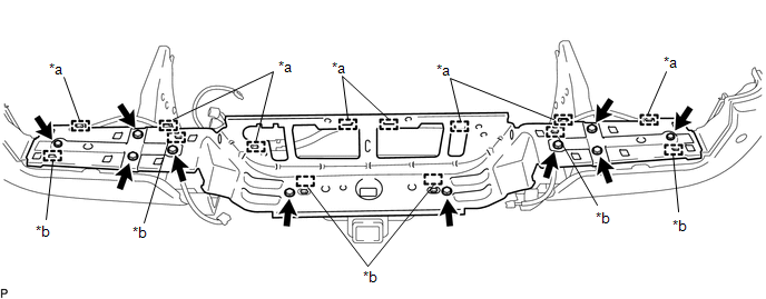 Text in Illustration
|
*a |
Wire Harness Clamp |
*b |
Guide |
(b) Remove the 10 bolts.
(c) Disengage the 6 guides to remove the rear bumper plate.
5. REMOVE REAR BUMPER EXTENSION LH
|
(a) Remove the 5 clips. Text in Illustration
|
|
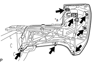
(b) Remove the clamp.
(c) w/ Clearance Sonar System:
(1) Disconnect the connector.
(d) Remove the rear bumper extension LH.
6. REMOVE REAR BUMPER EXTENSION RH
HINT:
Use the same procedure as for the LH side.
7. REMOVE NO. 1 ULTRASONIC SENSOR (w/ Clearance Sonar System)
8. REMOVE BLIND SPOT MONITOR SENSOR LH (w/ Blind Spot Monitor)
|
(a) Disconnect the connector. |
|
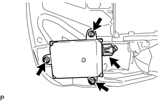
(b) Remove the 3 nuts and blind spot monitor sensor LH.
9. REMOVE BLIND SPOT MONITOR SENSOR RH (w/ Blind Spot Monitor)
HINT:
Use the same procedure as for the LH side.
10. REMOVE NO. 6 FLOOR WIRE
|
(a) Remove the 2 adhesive tapes. Text in Illustration
|
|
(b) Disengage the wire harness clamps to remove the No. 6 floor wire.
11. REMOVE REAR BUMPER SIDE STAY LH
|
(a) Remove the 2 bolts and rear bumper side stay LH. |
|
12. REMOVE REAR BUMPER SIDE STAY RH
HINT:
Use the same procedure as for the LH side.
 Removal
REMOVAL
CAUTION / NOTICE / HINT
HINT:
If the bumper is damaged, there is a possibility that the installation area of
the blind spot monitor sensor may be deformed and the blind spot monitor syste ...
 Reassembly
REASSEMBLY
PROCEDURE
1. INSTALL REAR BUMPER SIDE STAY LH
(a) Install the rear bumper side stay LH with the 2 bolts.
Torque:
30 N·m {306 kgf·cm, 22 ft·lbf}
...
Other materials:
Installation
INSTALLATION
PROCEDURE
1. INSTALL OIL COOLER TUBE
(a) Install the oil cooler tube to the vehicle body with the 2 bolts.
Torque:
28 N·m {286 kgf·cm, 21 ft·lbf}
2. INSTALL NO. 4 OIL COOLER INLET HOSE AND NO. 4 OIL COOLER OUTLET HOSE
NOTICE:
When connecting the hoses to the tube, su ...
Reassembly
REASSEMBLY
PROCEDURE
1. INSTALL MASTER CYLINDER RESERVOIR GROMMET
(a) Apply lithium soap base glycol grease to 2 new grommets.
(b) Install the 2 grommets onto the brake master cylinder reservoir.
2. INSTALL BRAKE MASTER CYLINDER RESERVOIR ASSEMBLY
(a) Install the brake master cylinder reservoi ...
Installation of a mobile two-way radio system
The installation of a mobile two-way radio system in your vehicle could affect
electronic systems such as: ● Multiport fuel injection system/sequential multiport
fuel injection system
● Cruise control system
● Anti-lock brake system
● SRS airbag system
● Seat be ...
