Toyota Tacoma (2015-2018) Service Manual: Inspection
INSPECTION
PROCEDURE
1. INSPECT TRANSMISSION FLOOR SHIFT ASSEMBLY (w/o Smart Key System)
HINT:
If the results of the following inspections are as specified but a malfunction has occurred, replace the transmission floor shift assembly.
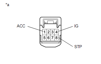
(a) Inspect the wire harness.
(1) Disconnect the shift lock control ECU connector.
|
(2) Measure the voltage according to the value(s) in the table below. Text in Illustration
Standard Voltage:
If the result is not as specified, repair or replace the wire harness or connector. |
|
|
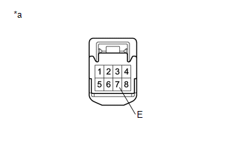
(3) Measure the resistance according to the value(s) in the table below. Text in Illustration
Standard Resistance:
If the result is not as specified, repair or replace the wire harness or connector. |
|
(b) Inspect the key interlock solenoid operation signal.
(1) Connect the shift lock control ECU connector.
|
(2) Measure the voltage according to the value(s) in the table below. Text in Illustration
Standard Voltage:
HINT: Do not disconnect the shift lock control ECU connector. If the result is not as specified, replace the transmission floor shift assembly. If the shift lock does not operate when the power source of the shift lock control ECU is normal and the resistance between the body ground and the shift lock control ECU is as specified, replace the transmission floor shift assembly. |
|
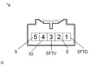
2. INSPECT TRANSMISSION FLOOR SHIFT ASSEMBLY (w/ Smart Key System)
HINT:
If the results of the following inspections are as specified but a malfunction has occurred, replace the transmission floor shift assembly.
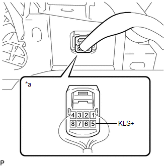
(a) Inspect the wire harness.
(1) Disconnect the shift lock control ECU connector.
|
(2) Measure the voltage according to the value(s) in the table below. Text in Illustration
Standard Voltage:
If the result is not as specified, repair or replace the wire harness or connector. |
|
|
(3) Measure the resistance according to the value(s) in the table below. Text in Illustration
Standard Resistance:
If the result is not as specified, repair or replace the wire harness or connector. If the shift lock does not operate when the power source of the shift lock control ECU is normal and the resistance between the body ground and the shift lock control ECU is as specified, replace the transmission floor shift assembly. |
|
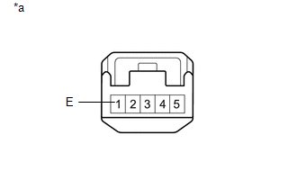
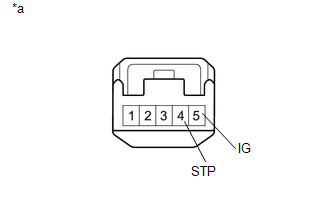
3. INSPECT TRANSMISSION CONTROL SWITCH (TRANSMISSION FLOOR SHIFT ASSEMBLY)
(a) Disconnect the transmission control switch connector.
|
(b) Measure the resistance according to the value(s) in the table below. Text in Illustration
Standard Resistance:
If the result is not as specified, replace the transmission floor shift assembly. |
|
 Removal
REMOVAL
PROCEDURE
1. REMOVE FRONT CONSOLE BOX
(See page )
2. DISCONNECT TRANSMISSION CONTROL CABLE ASSEMBLY
(a) Move the shift lever to N.
(b) Disconnect the end of the transmission control ca ...
 Installation
INSTALLATION
PROCEDURE
1. INSTALL TRANSMISSION FLOOR SHIFT ASSEMBLY
(a) Install the transmission floor shift assembly to the vehicle body with the
4 bolts.
Torque:
14 N·m {143 kgf·cm, 10 ft ...
Other materials:
Sound of Portable Player cannot be Heard from Speakers or Sound is Low
PROCEDURE
1.
CHECK PORTABLE PLAYER SETTINGS
(a) Check the portable player settings.
(1) Check that the volume is not set to "0".
(2) Check that the mute is off.
(b) Check that the sound of the portable player can be heard from the speakers.
OK:
Sound ...
Yaw Rate Sensor Malfunction (C1436)
DESCRIPTION
The skid control ECU (master cylinder solenoid) receives signals from the yaw
rate and acceleration (airbag sensor assembly) via the CAN communication system.
The airbag sensor assembly has a built-in yaw rate and acceleration sensor and
detects the vehicle's condition using 2 ...
Freeze Frame Data
FREEZE FRAME DATA
CHECK FREEZE FRAME DATA
HINT:
The ECU records vehicle and driving condition information as freeze frame data
the moment a DTC is stored.
(a) Connect the Techstream to the DLC3.
(b) Turn the ignition switch to ON.
(c) Turn the Techstream on.
(d) Enter the following menus: P ...
