Toyota Tacoma (2015-2018) Service Manual: All Doors LOCK/UNLOCK Functions do not Operate Via Door Control Switch
DESCRIPTION
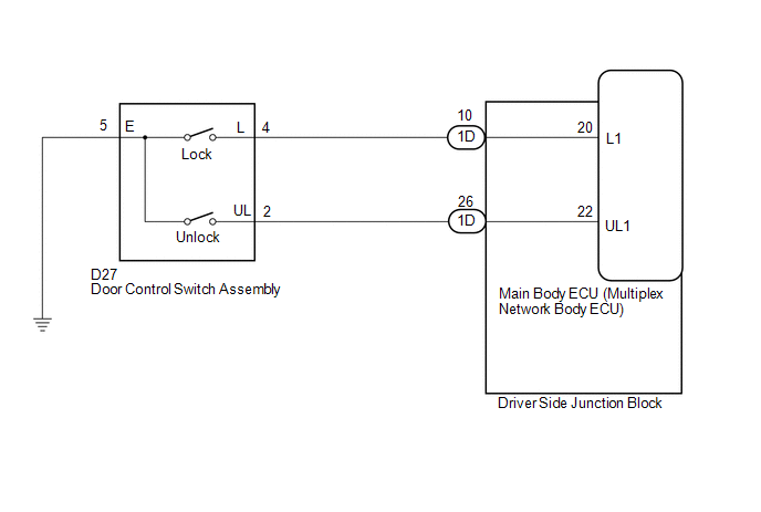
The main body ECU (multiplex network body ECU) receives switch signals from the door control switch assembly on the front passenger door and activates the door lock motor on each door according to these signals.
WIRING DIAGRAM
PROCEDURE
|
1. |
READ VALUE USING TECHSTREAM (Door Lock SW-Lock, Door Lock SW-Unlock) |
(a) Connect the Techstream to the DLC3.
(b) Turn the ignition switch to ON.
(c) Turn the Techstream on.
(d) Enter the following menus: Body Electrical / Main Body / Data List.
(e) Read the Data List according to the display on the Techstream.
Main Body|
Tester Display |
Measurement Item/Range |
Normal Condition |
Diagnostic Note |
|---|---|---|---|
|
Door Lock SW-Lock |
Door control switch (power window regulator master switch assembly) or door control switch assembly lock signal/ON or OFF |
ON: Lock side of door control switch (power window regulator master switch assembly) or door control switch assembly pushed OFF: Lock side of door control switch (power window regulator master switch assembly) and door control switch assembly not pushed |
- |
|
Door Lock SW-Unlock |
Door control switch (power window regulator master switch assembly) or door control switch assembly unlock signal/ON or OFF |
ON: Unlock side of door control switch (power window regulator master switch assembly) or door control switch assembly pushed OFF: Unlock side of door control switch (power window regulator master switch assembly) or door control switch assembly not pushed |
- |
OK:
The Techstream indicates ON or OFF according to the switch operation shown in the table.
| OK | .gif) |
REPLACE MAIN BODY ECU (MULTIPLEX NETWORK BODY ECU) |
|
.gif)
|
2. |
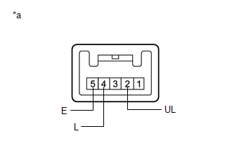
INSPECT DOOR CONTROL SWITCH ASSEMBLY |
(a) Remove the door control switch assembly (See page
.gif) ).
).
(b) Inspect the door control switch assembly.
|
(1) Measure the resistance according to the value(s) in the table below. Standard Resistance:
|
|
| NG | |
REPLACE DOOR CONTROL SWITCH ASSEMBLY |
|
|
3. |
CHECK HARNESS AND CONNECTOR (DOOR CONTROL SWITCH ASSEMBLY - MAIN BODY ECU (MULTIPLEX NETWORK BODY ECU)) |
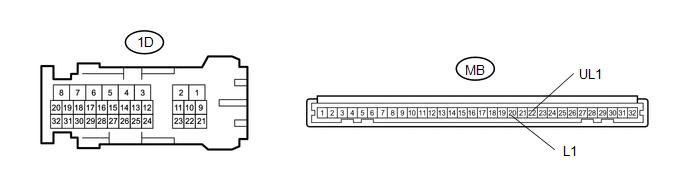
(a) Disconnect the 1D driver side junction block connector.
(b) Measure the resistance according to the value(s) in the table below.
Standard Resistance:
|
Tester Connection |
Condition |
Specified Condition |
|---|---|---|
|
D27-2 (UL) - 1D-26 (UL1) |
Always |
Below 1 Ω |
|
D27-4 (L) - 1D-10 (L1) |
Always |
Below 1 Ω |
|
D27-5 (E) - Body ground |
Always |
Below 1 Ω |
|
D27-2 (UL) - Body ground |
Always |
10 kΩ or higher |
|
D27-4 (L) - Body ground |
Always |
10 kΩ or higher |
| NG | |
REPAIR OR REPLACE HARNESS OR CONNECTOR |
|
|
4. |
CHECK DRIVER SIDE JUNCTION BLOCK |
(a) Remove the driver side junction block (See page
).
Standard Resistance:
|
Tester Connection |
Condition |
Specified Condition |
|---|---|---|
|
1D-16 - MB-22 (UL1) |
Always |
Below 1 Ω |
|
1D-23 - MB-20 (L1) |
Always |
Below 1 Ω |
|
1D-16 - Body ground |
Always |
10 kΩ or higher |
|
1D-23 (L1) - Body ground |
Always |
10 kΩ or higher |
|
*a |
Component without harness connected (driver side junction block) |
- |
- |
| OK | |
REPLACE MAIN BODY ECU (MULTIPLEX NETWORK BODY ECU) |
| NG | |
REPLACE DRIVER SIDE JUNCTION BLOCK |
 All Doors LOCK/UNLOCK Functions do not Operate Via Door Control Switch or Door
Key Cylinder
All Doors LOCK/UNLOCK Functions do not Operate Via Door Control Switch or Door
Key Cylinder
DESCRIPTION
The main body ECU (multiplex network body ECU) receives switch signals from the
power window regulator master switch assembly and driver door key cylinder lock
or unlock switch signal ...

Other materials:
Transfer System
Precaution
PRECAUTION
Before disassembly, clean the transfer assembly and remove any deposited
sand and mud to prevent it from entering the transfer during disassembly
and assembly.
When removing any light alloy parts such as the transfer covers, do
not pry them off with a ...
Cellular Phone Registration Failure, Phone Directory Transfer Failure
PROCEDURE
1.
CHECK OPERATION
(a) Place the cellular phone close to the navigation receiver assembly.
(b) Check if the cellular phone can be registered.
OK:
The cellular phone can be registered.
OK
NORMAL OPERATION
...
Customize Parameters
CUSTOMIZE PARAMETERS
CUSTOMIZE LANE DEPARTURE ALERT SYSTEM
NOTICE:
When the customer requests a change in a function, first make sure that
the function can be customized.
Be sure to make a note of the current settings before customizing.
When troubleshooting a function, fir ...
