Toyota Tacoma (2015-2018) Service Manual: Installation
INSTALLATION
PROCEDURE
1. INSTALL TRANSMISSION FLOOR SHIFT ASSEMBLY
(a) Install the transmission floor shift assembly to the vehicle body with the 4 bolts.
Torque:
14 N·m {143 kgf·cm, 10 ft·lbf}
(b) Attach the 4 clamps to connect the wire harness to the transmission floor shift assembly.
(c) Connect the 2 connectors to the transmission floor shift assembly.
2. CONNECT TRANSMISSION CONTROL CABLE ASSEMBLY
NOTICE:
Check that the park/neutral position switch and the shift lever are in N.
|
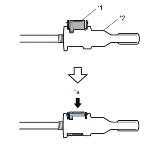
(a) Push the 2 claws together at the top of the transmission control cable lock piece. While holding the 2 claws together, push the 2 lugs on the bottom of the lock piece toward each other and upward to pull out the lock piece. Text in Illustration
|
|
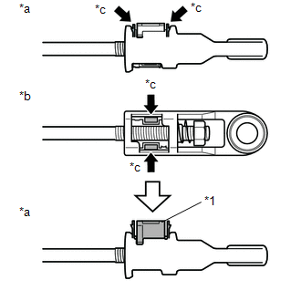
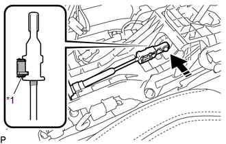
(b) Connect the transmission control cable assembly to the transmission floor shift assembly, and install a new clip.
(c) Connect the end of the transmission control cable assembly to the transmission floor shift assembly.
 Text in Illustration
|
*1 |
Lock Piece |
.png) |
Connect in this Direction |
NOTICE:
- The shift lever should be in N.
- Make sure that the lock piece is pulled up.
- Push on the end of the cable all the way to the base of the transmission floor shift assembly pin.
|
(d) Push the lock piece into the adjuster case. Text in Illustration
NOTICE: Securely push in the lock piece until it locks. |
|
3. INSPECT SHIFT LEVER POSITION
.gif)
4. INSTALL FRONT CONSOLE BOX
(See page )
 Inspection
INSPECTION
PROCEDURE
1. INSPECT TRANSMISSION FLOOR SHIFT ASSEMBLY (w/o Smart Key System)
HINT:
If the results of the following inspections are as specified but a malfunction
has occurred, replac ...
 Reassembly
REASSEMBLY
PROCEDURE
1. INSTALL INDICATOR LIGHT WIRE SUB-ASSEMBLY
(a) Connect the connector to install the indicator light wire sub-assembly
to the shift position indicator.
...
Other materials:
Problem Symptoms Table
PROBLEM SYMPTOMS TABLE
NOTICE:
After replacing the stereo component tuner assembly of vehicles subscribed
to pay-type satellite radio broadcasts, XM radio ID registration is necessary
(w/ SDARS System).
HINT:
Use the table below to help determine the cause of proble ...
Taillight Relay Circuit
DESCRIPTION
The main body ECU (multiplex network body ECU) controls the operation of the
TAIL relay.
WIRING DIAGRAM
CAUTION / NOTICE / HINT
NOTICE:
Inspect the fuses for circuits related to this system before performing
the following inspection procedure.
If the main body EC ...
Problem Symptoms Table
PROBLEM SYMPTOMS TABLE
HINT:
Use the table below to help determine the cause of problem symptoms.
If multiple suspected areas are listed, the potential causes of the symptoms
are listed in order of probability in the "Suspected Area" column of the
table. Check each sy ...
