Toyota Tacoma (2015-2018) Service Manual: Removal
REMOVAL
PROCEDURE
1. REMOVE FRONT CONSOLE BOX
(See page .gif) )
)
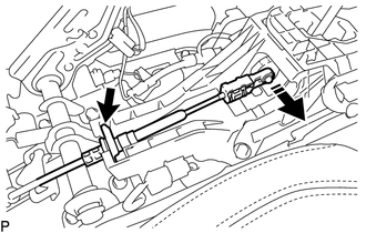
2. DISCONNECT TRANSMISSION CONTROL CABLE ASSEMBLY
(a) Move the shift lever to N.
(b) Disconnect the end of the transmission control cable assembly from the transmission floor shift assembly.
 Text in Illustration
.png) |
Disconnect in this Direction |
(c) Remove the clip to disconnect the transmission control cable assembly from the transmission floor shift assembly.
3. REMOVE TRANSMISSION FLOOR SHIFT ASSEMBLY
|
(a) Disconnect the 2 connectors from the transmission floor shift assembly. |
|
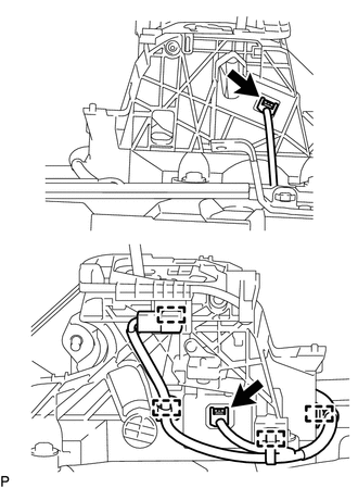
(b) Detach the 4 clamps to disconnect the wire harness from the transmission floor shift assembly.
|
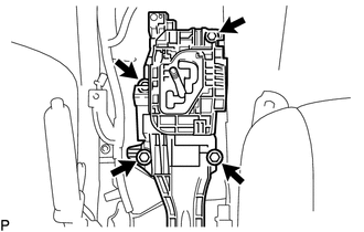
(c) Remove the 4 bolts and transmission floor shift assembly from the vehicle body. |
|
 On-vehicle Inspection
ON-VEHICLE INSPECTION
PROCEDURE
1. INSPECT SHIFT LEVER POSITION
(a) When moving the shift lever from P to each position with the ignition switch
ON and the brake pedal depressed, check that the s ...
 Inspection
INSPECTION
PROCEDURE
1. INSPECT TRANSMISSION FLOOR SHIFT ASSEMBLY (w/o Smart Key System)
HINT:
If the results of the following inspections are as specified but a malfunction
has occurred, replac ...
Other materials:
How To Proceed With Troubleshooting
CAUTION / NOTICE / HINT
HINT:
Use these procedure to troubleshoot the seat belt warning system.
*: Use the Techstream.
PROCEDURE
1.
VEHICLE BROUGHT TO WORKSHOP
NEXT
2 ...
Millimeter Wave Radar Sensor Communication Stop Mode
DESCRIPTION
Detection Item
Symptom
Trouble Area
Millimeter Wave Radar Sensor Communication Stop Mode
Either Condition is met:
Communication stop for "Front Radar" is indicated on the "Communication
Bus C ...
Components
COMPONENTS
ILLUSTRATION
ILLUSTRATION
ILLUSTRATION
ILLUSTRATION
ILLUSTRATION
ILLUSTRATION
ILLUSTRATION
ILLUSTRATION
ILLUSTRATION
ILLUSTRATION
...
