Toyota Tacoma (2015-2018) Service Manual: Speaker Output Short (B15C3)
DESCRIPTION
This DTC is stored when a malfunction occurs in the speakers.
|
DTC No. |
DTC Detection Condition |
Trouble Area |
|---|---|---|
|
B15C3 |
A short is detected in the speaker output circuit. |
|
WIRING DIAGRAM
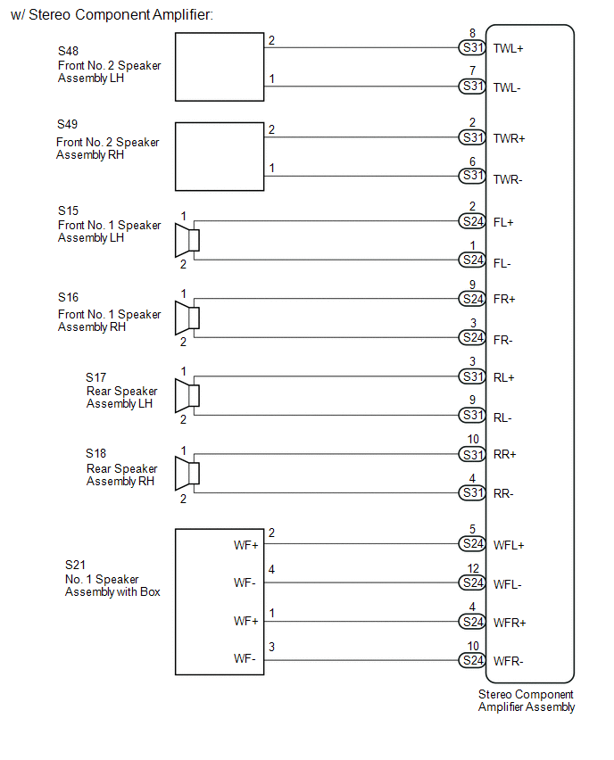
.png)
PROCEDURE
|
1. |
CHECK VEHICLE CONDITION |
(a) Check vehicle condition.
Result|
Result |
Proceed to |
|---|---|
|
w/ Stereo Component Amplifier |
A |
|
w/o Stereo Component Amplifier |
B |
| B | .gif) |
GO TO STEP 7 |
|
.gif)
|
2. |
CHECK HARNESS AND CONNECTOR (STEREO COMPONENT AMPLIFIER ASSEMBLY - BODY GROUND) |
(a) Disconnect the S24 and S31 stereo component amplifier assembly connectors.
(b) Disconnect the S15 and S16 front No. 1 speaker assembly connectors.
(c) Disconnect the S48 and S49 front No. 2 speaker assembly connectors.
(d) Disconnect the S17 and S18 rear speaker assembly connectors.
(e) Disconnect the S21 No. 1 speaker assembly with box connector.
(f) Measure the resistance between the stereo component amplifier assembly and body ground to check for a short circuit in the wire harness.
Standard Resistance:
|
Tester Connection |
Condition |
Specified Condition |
|---|---|---|
|
S24-2 (FL+) - Body ground |
Always |
10 kΩ or higher |
|
S24-1 (FL-) - Body ground |
Always |
10 kΩ or higher |
|
S24-9 (FR+) - Body ground |
Always |
10 kΩ or higher |
|
S24-3 (FR-) - Body ground |
Always |
10 kΩ or higher |
|
S31-8 (TWL+) - Body ground |
Always |
10 kΩ or higher |
|
S31-7 (TWL-) - Body ground |
Always |
10 kΩ or higher |
|
S31-2 (TWR+) - Body ground |
Always |
10 kΩ or higher |
|
S31-6 (TWR-) - Body ground |
Always |
10 kΩ or higher |
|
S31-3 (RL+) - Body ground |
Always |
10 kΩ or higher |
|
S31-9 (RL-) - Body ground |
Always |
10 kΩ or higher |
|
S31-10 (RR+) - Body ground |
Always |
10 kΩ or higher |
|
S31-4 (RR-) - Body ground |
Always |
10 kΩ or higher |
|
S24-5 (WFL+) - Body ground |
Always |
10 kΩ or higher |
|
S24-12 (WFL-) - Body ground |
Always |
10 kΩ or higher |
|
S24-4 (WFR+) - Body ground |
Always |
10 kΩ or higher |
|
S24-10 (WFR-) - Body ground |
Always |
10 kΩ or higher |
| NG | |
REPAIR OR REPLACE HARNESS OR CONNECTOR |
|
|
3. |
INSPECT FRONT NO. 1 SPEAKER ASSEMBLY |
|
(a) Remove front No. 1 speaker assembly (See page
|
|
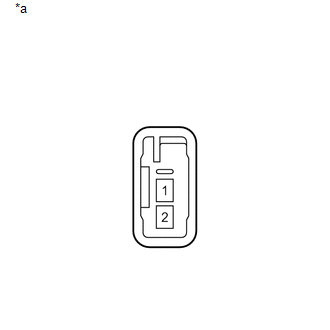
(b) Measure the resistance according to the value(s) in the table below.
Standard Resistance:
|
Tester Connection |
Condition |
Specified Condition |
|---|---|---|
|
1 - 2 |
Always |
3.2 to 4.8Ω |
|
*a |
Component without harness connected (Front No. 1 Speaker Assembly) |
| NG | |
REPAIR OR REPLACE HARNESS OR CONNECTOR |
|
|
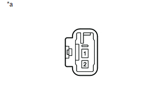
4. |
INSPECT FRONT NO. 2 SPEAKER ASSEMBLY |
|
(a) Remove front No. 2 speaker assembly (See page
|
|
(b) Measure the resistance according to the value(s) in the table below.
Standard Resistance:
|
Tester Connection |
Condition |
Specified Condition |
|---|---|---|
|
1 - 2 |
Always |
1.5 to 2.5 Ω |
|
*a |
Component without harness connected (Front No. 2 Speaker Assembly) |
| NG | |
REPLACE FRONT NO. 2 SPEAKER ASSEMBLY |
|
|
5. |
INSPECT REAR SPEAKER ASSEMBLY |
|
(a) Disconnect the S17 and S18 rear speaker assembly connectors. |
|
(b) Measure the resistance according to the value(s) in the table below.
Standard Resistance:
|
Tester Connection |
Condition |
Specified Condition |
|---|---|---|
|
1 - 2 |
Always |
4 Ω |
|
*a |
Component without harness connected (Rear Speaker Assembly) |
| NG | |
REPLACE REAR SPEAKER ASSEMBLY |
|
|
6. |
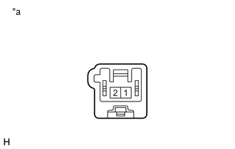
INSPECT NO. 1 SPEAKER ASSEMBLY WITH BOX |
|
(a) Disconnect the S21 No. 1 speaker assembly with box connector. |
|
(b) Measure the resistance according to the value(s) in the table below.
Standard Resistance:
|
Tester Connection |
Condition |
Specified Condition |
|---|---|---|
|
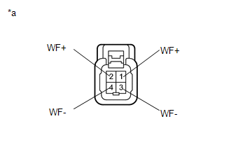
2 (WF+) - 4 (WF-) |
Always |
1.6 to 2.4 Ω |
|
1 (WF+) - 3 (WF-) |
Always |
1.6 to 2.4 Ω |
|
*a |
Component without harness connected (No. 1 Speaker Assembly with Box) |
| OK | |
REPLACE STEREO COMPONENT AMPLIFIER ASSEMBLY |
| NG | |
REPLACE NO. 1 SPEAKER ASSEMBLY WITH BOX |
|
7. |
CHECK HARNESS AND CONNECTOR (NAVIGATION RECEIVER ASSEMBLY - BODY GROUND) |
(a) Disconnect the N23 and N24 navigation receiver assembly connectors.
(b) Disconnect the S46 and S47 front No. 2 speaker assembly connectors.
(c) Disconnect the S17 and S18 rear speaker assembly connectors.
(d) Measure the resistance between the navigation receiver assembly to check for a short circuit in the wire harness.
Standard Resistance:
|
Tester Connection |
Condition |
Specified Condition |
|---|---|---|
|
N24-1 (FR+) - Body ground |
Always |
10 kΩ or higher |
|
N24-5 (FR-) - Body ground |
Always |
10 kΩ or higher |
|
N24-2 (FL+) - Body ground |
Always |
10 kΩ or higher |
|
N24-6 (FL-) - Body ground |
Always |
10 kΩ or higher |
|
N23-1 (RR+) - Body ground |
Always |
10 kΩ or higher |
|
N23-3 (RR-) - Body ground |
Always |
10 kΩ or higher |
|
N23-2 (RL+) - Body ground |
Always |
10 kΩ or higher |
|
N23-6 (RL-) - Body ground |
Always |
10 kΩ or higher |
| NG | |
REPAIR OR REPLACE HARNESS OR CONNECTOR |
|
|
8. |
CHECK HARNESS AND CONNECTOR (FRONT NO. 2 SPEAKER ASSEMBLY - BODY GROUND) |
(a) Disconnect the S15 and S16 front No. 1 speaker assembly connectors.
(b) Disconnect the S46 and S47 front No. 2 speaker assembly connectors.
(c) Measure the resistance between each of the front No. 2 speaker assemblies and body ground to check for a short circuit in the wire harness.
Standard Resistance:
|
Tester Connection |
Condition |
Specified Condition |
|---|---|---|
|
S47-1 (+) - Body ground |
Always |
10 kΩ or higher |
|
S47-3 (-) - Body ground |
Always |
10 kΩ or higher |
|
S46-1 (+) - Body ground |
Always |
10 kΩ or higher |
|
S46-3 (-) - Body ground |
Always |
10 kΩ or higher |
| NG | |
REPAIR OR REPLACE HARNESS OR CONNECTOR |
|
|
9. |
INSPECT FRONT NO. 1 SPEAKER ASSEMBLY |
|
(a) Remove front No. 1 speaker assembly (See page
|
|
(b) Measure the resistance according to the value(s) in the table below.
Standard Resistance:
|
Tester Connection |
Condition |
Specified Condition |
|---|---|---|
|
1 - 2 |
Always |
3.2 to 4.8 Ω |
|
*a |
Component without harness connected (Front No. 1 Speaker Assembly) |
| NG | |
REPLACE FRONT NO. 1 SPEAKER ASSEMBLY |
|
|
10. |
INSPECT FRONT NO. 2 SPEAKER ASSEMBLY |
|
(a) Remove front No. 2 speaker assembly (See page
|
|
(b) Measure the resistance according to the value(s) in the table below.
Standard Resistance:
|
Tester Connection |
Condition |
Specified Condition |
|---|---|---|
|
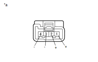
2 (+) - 4(-) |
Always |
10 kΩ or higher |
|
2 (+) - 1(+) |
Always |
Below 1 Ω |
|
4 (-) - 3(-) |
Always |
Below 1 Ω |
|
*a |
Component without harness connected (Front No. 2 Speaker Assembly) |
| NG | |
REPLACE FRONT NO. 2 SPEAKER ASSEMBLY |
|
|
11. |
REPLACE FRONT NO. 2 SPEAKER ASSEMBLY |
(a) Replace the front No. 2 speaker assembly with a new or known good one (See
page .gif) ).
).
(b) Clear the DTCs (See page ).
(c) Recheck for DTCs and check that no DTCs are output.
OK:
No DTCs are output.
HINT:
- Connect all the connectors to the front No. 2 speaker assemblies that were disconnected.
- When there is a possibility that either the right or left front No. 2 speaker assembly is defective, inspect by interchanging the right one with the left one.
- Perform the above inspection on both the LH and RH side.
| OK | |
END |
|
|
12. |
INSPECT REAR SPEAKER ASSEMBLY |
|
(a) Remove rear speaker assembly (See page
|
|

(b) Measure the resistance according to the value(s) in the table below.
Standard Resistance:
|
Tester Connection |
Condition |
Specified Condition |
|---|---|---|
|
1 - 2 |
Always |
4 Ω |
|
*a |
Component without harness connected (Rear Speaker Assembly) |
| OK | |
REPLACE NAVIGATION RECEIVER ASSEMBLY |
| NG | |
REPLACE REAR SPEAKER ASSEMBLY |
 XM Tuner Antenna Disconnected (B15FE,B15FF)
DESCRIPTION
These DTCs are stored when a malfunction occurs in the antenna assembly with
holder which is connected to the navigation receiver assembly assembly.
DTC No.
DTC D ...
 Sending Malfunction (Navigation to APGS) (U0073,U0100,U0129,U0140,U0155,U0164)
DESCRIPTION
These DTCs are stored when a malfunction occurs in the CAN communication circuit.
DTC Code
DTC Detection Condition
Trouble Area
U0073
...
Other materials:
Precaution
PRECAUTION
1. IGNITION SWITCH EXPRESSIONS
(a) The type of ignition switch used on this model differs according to the specifications
of the vehicle. The expressions listed in the table below are used in this section.
Expression
Ignition Switch (Position)
Engine ...
Motor Circuit Malfunction (C1428)
DESCRIPTION
DTC No.
Detection Item
DTC Detection Condition
Trouble Area
C1428
Motor Circuit Malfunction
With the motor relay and motor fail-safe relay OFF, open or short in
motor circuit continues for 2 seconds o ...
System Description
SYSTEM DESCRIPTION
PRE-COLLISION SYSTEM DESCRIPTION
(a) The pre-collision system uses the pre-collision warning control, pre-collision
brake assist control and pre-collision braking control to help avoid a collision
or reduce the impact if it determines that the possibility of a collision is h ...
