Toyota Tacoma (2015-2018) Service Manual: Power Window Motor Malfunction (B2311)
DESCRIPTION
The power window regulator motor assemblies are operated by the power window regulator master switch assembly, front power window regulator switch assembly RH. The power window regulator motor assemblies have motor, regulator and ECU functions.
This DTC is output when the power window regulator motor assembly has a malfunction, or the ECU built into the regulator motor assembly determines that the fully closed window position has deviated approximately 20 mm (0.787 in.) or more from the normal position.
HINT:
DTC B2311 can be stored in each power window regulator motor assembly (power window ECU).
D-Door Motor (Front Power Window Regulator Motor Assembly LH)|
DTC No. |
DTC Detection Condition |
Trouble Area |
|---|---|---|
|
B2311 |
|
|
|
DTC No. |
DTC Detection Condition |
Trouble Area |
|---|---|---|
|
B2311 |
|
|
CAUTION / NOTICE / HINT
NOTICE:
- DTC B2311 is stored in each power window regulator motor assembly.
- If a power window regulator motor assembly has been replaced with a
new one, initialize the power window control system (See page
.gif) ).
). - If a power window regulator motor assembly and door window regulator
sub-assembly have been removed and installed, or if a power window regulator
motor assembly was reused when a door glass or door glass run was replaced,
initialize the power window control system (See page
).
- The power window control system uses the LIN communication system. Inspect
the communication function by following How to Proceed with Troubleshooting.
Troubleshoot the power window control system after confirming that the communication
system is functioning properly (See page
).
PROCEDURE
|
1. |
CHECK FOR DTC |
(a) Clear the DTCs (See page ).
(b) Check for DTCs (See page ).
OK:
DTC B2311 is not output.
| OK | .gif) |
USE SIMULATION METHOD TO CHECK |
|
.gif)
|
2. |
CHECK DTC OUTPUT |
(a) Check the parts which the DTCs have been output from.
Result|
Result |
Proceed to |
|---|---|
|
DTC output from power window regulator motor assembly (for driver door) |
A |
|
DTC output from power window regulator motor assembly (for front passenger door) |
B |
| B | |
GO TO STEP 4 |
|
|
3. |
CHECK HARNESS AND CONNECTOR (FRONT POWER WINDOW REGULATOR MOTOR ASSEMBLY LH - BATTERY AND BODY GROUND) |
|
(a) Measure the resistance according to the value(s) in the table below. Standard Resistance:
|
|
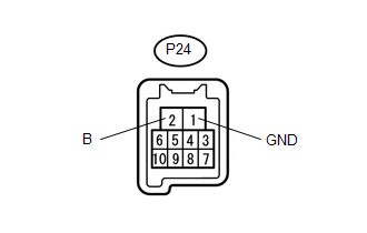
(b) Measure the voltage according to the value(s) in the table below.
Standard Voltage:
|
Tester Connection |
Condition |
Specified Condition |
|---|---|---|
|
P24-2 (B) - P24-1 (GND) |
Always |
11 to 14 V |
|
Result |
Proceed to |
|---|---|
|
NG |
A |
|
OK |
B |
| A | |
REPAIR OR REPLACE HARNESS OR CONNECTOR |
| B | |
GO TO STEP 5 |
|
4. |
CHECK HARNESS AND CONNECTOR (FRONT POWER WINDOW REGULATOR MOTOR ASSEMBLY LH - BATTERY AND BODY GROUND) |
|
(a) Measure the resistance according to the value(s) in the table below. Standard Resistance:
|
|
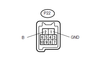
(b) Measure the voltage according to the value(s) in the table below.
Standard Voltage:
|
Tester Connection |
Condition |
Specified Condition |
|---|---|---|
|
P22-2 (B) - P22-1 (GND) |
Always |
11 to 14 V |
| NG | |
REPAIR OR REPLACE HARNESS OR CONNECTOR |
|
|
5. |
PERFORM ACTIVE TEST USING TECHSTREAM (APPLICABLE LOCATION) |
(a) Connect the Techstream to the DLC3.
(b) Turn the ignition switch to ON.
(c) Turn the Techstream on.
(d) Enter the following menus: Body Electrical / (desired system) / Active Test.
HINT:
Perform the Active Test for the power window regulator motor assembly that has DTC B2311 stored in its ECU
(e) Perform the Active Test according to the display on the Techstream.
CAUTION:
Be careful to avoid injuries as this test causes vehicle parts to move. During the Active Test, the jam protection function will not operate.
D-Door Motor (Front Power Window Regulator Motor Assembly LH)|
Tester Display |
Test Part |
Control Range |
Diagnostic Note |
|---|---|---|---|
|
Power Window |
Power window |
OFF / UP / DOWN |
- |
|
Tester Display |
Test Part |
Control Range |
Diagnostic Note |
|---|---|---|---|
|
Power Window |
Power window |
OFF / UP / DOWN |
- |
OK:
Each power window motor operates.
Result|
Result |
Proceed to |
|---|---|
|
OK |
A |
|
NG (Driver side power window) |
B |
|
NG (Front passenger side power window) |
C |
| B | |
REPLACE FRONT POWER WINDOW REGULATOR MOTOR ASSEMBLY LH |
| C | |
REPLACE FRONT POWER WINDOW REGULATOR MOTOR ASSEMBLY RH |
|
|
6. |
PERFORM INITIALIZATION (APPLICABLE LOCATION) |
(a) Initialize the power window regulator motor assembly (See page
).
HINT:
Check the power window operation of the window where DTC B2311 has been stored.
|
|
7. |
CHECK POWER WINDOW CONTROL SYSTEM (APPLICABLE LOCATION) |
(a) Check that the power window operates normally by opening and closing the window.
HINT:
Check the power window operation of the window where DTC B2311 has been stored.
OK:
Each power window operates normally.
Result|
Result |
Proceed to |
|---|---|
|
OK |
A |
|
NG (Driver side power window) |
B |
|
NG (Front passenger side power window) |
C |
| B | |
REPLACE FRONT POWER WINDOW REGULATOR MOTOR ASSEMBLY LH |
| C | |
REPLACE FRONT POWER WINDOW REGULATOR MOTOR ASSEMBLY RH |
|
|
8. |
CHECK WHETHER PARTS HAVE BEEN INSTALLED CORRECTLY |
(a) Check that the power window components are installed correctly.
OK:
Power window components are installed correctly.
| NG | |
INSTALL PARTS CORRECTLY |
|
|
9. |
CHECK DTC OUTPUT |
(a) Turn the ignition switch to ON.
(b) Wait for at least 10 seconds, and then turn the ignition switch to ON.
(c) Check for DTCs (See page ).
|
Result |
Proceed to |
|---|---|
|
OK |
A |
|
NG (Driver side power window) |
B |
|
NG (Front passenger side power window) |
C |
| A | |
END |
| B | |
REPLACE FRONT POWER WINDOW REGULATOR MOTOR ASSEMBLY LH |
| C | |
REPLACE FRONT POWER WINDOW REGULATOR MOTOR ASSEMBLY RH |
 Fail-safe Chart
FAIL-SAFE CHART
1. PULSE FAILURE OR DISPLACEMENT OF NON-DETECTION RANGE TO THE OPENING DIRECTION
(a) If the pulse sensor built into the power window regulator motor malfunctions,
the power window ...
 Power Window Switch Malfunction (B2312)
DESCRIPTION
The power window regulator motor assembly is operated by the power window regulator
master switch assembly or power window regulator switch assembly. The power window
regulator motor ...
Other materials:
Diagnostic Trouble Code Chart
DIAGNOSTIC TROUBLE CODE CHART
Navigation System
DTC Code
Detection Item
See page
B1324
Lost Communication with Meter
B1532
LVDS Signal Malfunction (from Extension Module)
...
Disposal
DISPOSAL
CAUTION / NOTICE / HINT
CAUTION:
Before performing pre-disposal deployment of any SRS part, review and closely
follow all applicable environmental and hazardous material regulations. Pre-disposal
deployment may be considered hazardous material treatment.
PROCEDURE
1. PRECAUTION
...
Installation
INSTALLATION
PROCEDURE
1. INSTALL INTAKE MANIFOLD
(a) Set 2 new No. 1 intake manifold to head gaskets on cylinder head
sub-assembly and cylinder head LH as shown in the illustration.
NOTICE:
Align the port holes of the gasket and cylinder head sub-assembly
...
