Toyota Tacoma (2015-2018) Service Manual: Voltage Inverter
Components
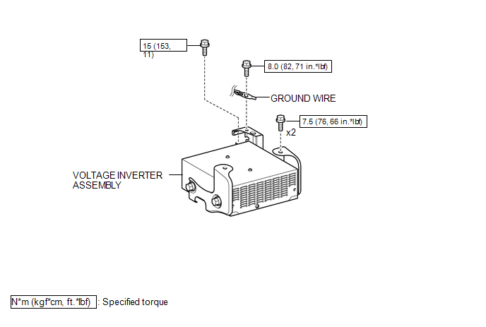
COMPONENTS
ILLUSTRATION
Inspection
INSPECTION
PROCEDURE
1. INSPECT VOLTAGE INVERTER ASSEMBLY
(a) Check the voltage inverter assembly.
(1) Measure the voltage according to the value(s) in the table below.
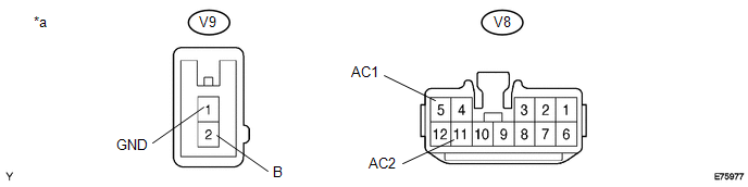 Text in Illustration
|
*a |
Component with harness connected (Voltage Inverter Assembly) |
- |
- |
Standard:
|
Tester Connection |
Switch Condition |
Specified Condition |
|---|---|---|
|
V9-2 (B) - V9-1 (GND) |
Ignition switch (ON) |
11 to 15 V |
|
V9-1 (GND) - Body ground |
Always |
Below 1 V |
|
V8-5 (AC1) - V8-11 (AC2) |
Ignition switch (ON) Main switch (ON) |
108 to 132 V |
If the result is not as specified, replace the voltage inverter assembly.
Removal
REMOVAL
PROCEDURE
1. REMOVE REAR CONSOLE BOX ASSEMBLY
(See page .gif) )
)
2. REMOVE VOLTAGE INVERTER ASSEMBLY
|
(a) Remove the bolt to disconnect the ground wire. |
|
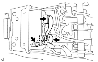
(b) Disconnect the 2 connectors and disengage the clamp.
|
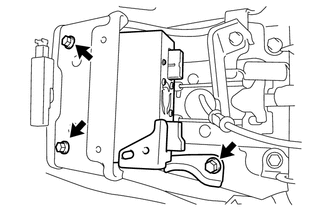
(c) Remove the 3 bolts and voltage inverter assembly. |
|
Installation
INSTALLATION
PROCEDURE
1. INSTALL VOLTAGE INVERTER ASSEMBLY
(a) Temporarily install the voltage inverter assembly with the 3 bolts.
|
(b) Tighten the 2 bolts in the order shown in the illustration. Torque: 7.5 N·m {76 kgf·cm, 66 in·lbf} |
|
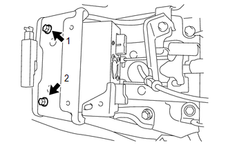
|
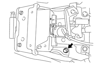
(c) Tighten the bolt. Torque: 15 N·m {153 kgf·cm, 11 ft·lbf} |
|
(d) Connect the 2 connectors and engage the clamp.
(e) Connect the ground wire with the bolt.
Torque:
8.0 N·m {82 kgf·cm, 71 in·lbf}
2. INSTALL REAR CONSOLE BOX ASSEMBLY
(See page .gif) )
)
 Rear Power Outlet Switch
Components
COMPONENTS
ILLUSTRATION
Inspection
INSPECTION
PROCEDURE
1. INSPECT MAIN SWITCH ASSEMBLY
(a) Check the main switch assembly.
(1) Measure the resistance according to ...
 Wireless Charger Assembly
Components
COMPONENTS
ILLUSTRATION
Removal
REMOVAL
PROCEDURE
1. REMOVE FRONT CONSOLE BOX
(See page
)
2. REMOVE MOBILE WIRELESS CHARGER CRADLE ASSEMBLY
(a) Remove the 5 sc ...
Other materials:
Installation
INSTALLATION
PROCEDURE
1. INSTALL TRANSMISSION WIRE
(a) Coat 2 new O-rings with ATF, and install them to the 2 temperature sensors.
(b) Coat a new O-ring with ATF, and install it to the transmission wire.
(c) Install the transmission wire to the automatic transmission case sub-assembly
with t ...
Removal
REMOVAL
PROCEDURE
1. PRECAUTION
NOTICE:
After turning the engine switch off, waiting time may be required before disconnecting
the cable from the battery terminal. Therefore, make sure to read the disconnecting
the cable from the battery terminal notice before proceeding with work.
Click he ...
Wireless Charger Main Switch
Components
COMPONENTS
ILLUSTRATION
Removal
REMOVAL
PROCEDURE
1. REMOVE INSTRUMENT PANEL LOWER CENTER FINISH PANEL
(See page )
2. REMOVE MOBILE WIRELESS CHARGER SWITCH
(a) Disengage the 2 claws to remove the mobile wireless charger switch.
...
