Toyota Tacoma (2015-2018) Service Manual: Main Switch Illumination Circuit
DESCRIPTION
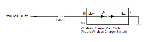
When the light control switch is turned to the tail or head position, this circuit sends an illumination signal to the wireless charger main switch (mobile wireless charger switch). Based on this signal, the wireless charger main switch (mobile wireless charger switch) is illuminated.
WIRING DIAGRAM
CAUTION / NOTICE / HINT
NOTICE:
Inspect the fuses for circuits related to this system before performing the following inspection procedure.
PROCEDURE
|
1. |
CHECK HARNESS AND CONNECTOR (ILLUMINATION SIGNAL) |
(a) Disconnect the M7 wireless charger main switch (mobile wireless charger switch) connector.
(b) Measure the voltage according to the value(s) in the table below.
Standard Voltage:
|
Tester Connection |
Switch Condition |
Specified Condition |
|---|---|---|
|
M7-10 (ILL+) - Body ground |
Light control switch in tail or head position |
11 to 14 V |
| NG | .gif) |
REPAIR OR REPLACE HARNESS OR CONNECTOR |
|
.gif)
|
2. |
CHECK HARNESS AND CONNECTOR (WIRELESS CHARGER MAIN SWITCH - BODY GROUND) |
(a) Disconnect the M7 wireless charger main switch (mobile wireless charger switch) connector.
(b) Measure the resistance according to the value(s) in the table below.
Standard Resistance:
|
Tester Connection |
Condition |
Specified Condition |
|---|---|---|
|
M7-9 (ILL-) - Body ground |
Always |
Below 1 Ω |
| OK | |
PROCEED TO NEXT SUSPECTED AREA SHOWN IN PROBLEM SYMPTOMS TABLE |
| NG | |
REPAIR OR REPLACE HARNESS OR CONNECTOR |
 Wireless Charger Illumination Circuit
DESCRIPTION
When the light control switch is turned to the tail or head position, this circuit
sends an illumination signal to the mobile wireless charger cradle assembly. Based
on this signal, t ...
 Pre-collision
...
Other materials:
Sun visors
Type A
Forward position: Flip down.
Side position: Flip down, unhook,
and swing to the side.
Type B
Forward position: Flip down.
Side position: Flip down, unhook,
and swing to the side.
Side extender: Place in side position,
then slide backwards. ...
Open in Pump Motor Circuit (C1251)
DESCRIPTION
The motor relay (semiconductor relay) is built into the master cylinder solenoid
and drives the pump motor based on a signal from the skid control ECU (master cylinder
solenoid).
DTC No.
DTC Detecting Condition
Trouble Areas
C1251
...
Removal
REMOVAL
PROCEDURE
1. REMOVE SPIRAL CABLE WITH SENSOR SUB-ASSEMBLY
(See page )
2. REMOVE WINDSHIELD WIPER SWITCH ASSEMBLY
3. REMOVE HEADLIGHT DIMMER SWITCH ASSEMBLY
(a) Disconnect the connector.
(b) Disengage the 3 claws to remove the he ...
