Toyota Tacoma (2015-2018) Service Manual: High Beam Headlight Circuit
DESCRIPTION
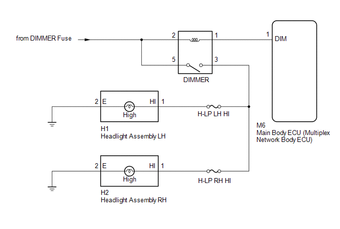
The main body ECU (multiplex network body ECU) controls the high beam headlights.
WIRING DIAGRAM
CAUTION / NOTICE / HINT
NOTICE:
- Inspect the fuses for circuits related to this system before performing the following inspection procedure.
- If the main body ECU (multiplex network body ECU) is replaced, refer
to Registration (See page
.gif) ).*1
).*1
- *1: w/ Smart Key System
PROCEDURE
|
1. |
PERFORM ACTIVE TEST USING TECHSTREAM (HEAD LIGHT Hi) |
(a) Connect the Techstream to the DLC3.
(b) Turn the ignition switch to ON.
(c) Turn the Techstream on.
(d) Enter the following menus: Body Electrical / Main Body / Active Test.
(e) Perform the Active Test according to the display on the Techstream.
Main Body|
Tester Display |
Test Part |
Control Range |
Diagnostic Note |
|---|---|---|---|
|
Head Light Hi |
High beam headlights |
ON/OFF |
- |
OK:
High beam headlights illuminate.
| OK | .gif) |
PROCEED TO NEXT SUSPECTED AREA SHOWN IN PROBLEM SYMPTOMS TABLE |
|
.gif)
|
2. |
INSPECT DIMMER RELAY |
|
(a) Remove the headlight dimmer relay from the engine room relay block. |
|
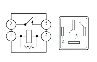
(b) Measure the resistance according to the value(s) in the table below.
Standard Resistance:
|
Tester Connection |
Condition |
Specified Condition |
|---|---|---|
|
3 - 5 |
Voltage is not applied between terminals 1 and 2 |
10 kΩ or higher |
|
3 - 5 |
Voltage is applied between terminals 1 and 2 |
Below 1 Ω |
| NG | |
REPLACE DIMMER RELAY |
|
|
3. |
CHECK HARNESS AND CONNECTOR (BATTERY - DIMMER RELAY) |
(a) Measure the voltage according to the value(s) in the table below.
Standard Voltage:
|
Tester Connection |
Condition |
Specified Condition |
|---|---|---|
|
Relay terminal 2 - Body ground |
Always |
11 to 14 V |
|
Relay terminal 5 - Body ground |
Always |
11 to 14 V |
| NG | |
REPAIR OR REPLACE HARNESS OR CONNECTOR |
|
|
4. |
CHECK HARNESS AND CONNECTOR (DIMMER RELAY - MAIN BODY ECU (MULTIPLEX NETWORK BODY ECU) |
(a) Disconnect the M6 main body ECU (multiplex network body ECU) connector.
(b) Measure the resistance according to the value(s) in the table below.
Standard Resistance:
|
Tester Connection |
Condition |
Specified Condition |
|---|---|---|
|
Relay terminal 1 - M6-1 (DIM) |
Always |
Below 1 Ω |
|
M6-1 (DIM) - Body ground |
Always |
10 kΩ or higher |
| OK | |
REPLACE MAIN BODY ECU (MULTIPLEX NETWORK BODY ECU) |
| NG | |
REPAIR OR REPLACE HARNESS OR CONNECTOR |
 Door Unlock Detection Switch Circuit
DESCRIPTION
The main body ECU (multiplex network body ECU) detects the condition of each
door unlock detection switch.
WIRING DIAGRAM
CAUTION / NOTICE / HINT
NOTICE:
If the main body ECU (mul ...
 Low Beam Headlight Circuit
DESCRIPTION
The main body ECU (multiplex network body ECU) controls the low beam headlights.
WIRING DIAGRAM
CAUTION / NOTICE / HINT
NOTICE:
Inspect the fuses for circuits related to thi ...
Other materials:
Air conditioning filter
The air conditioning filter must be changed regularly to maintain air conditioning
efficiency.
■ Removal method
Turn the engine switch to the LOCK
position.
Open the glove box.
Slide off the damper.
Push in each side of the glove box to disconnect the claws.
Open the filter ...
Problem Symptoms Table
PROBLEM SYMPTOMS TABLE
HINT:
Use the table below to help determine the cause of problem symptoms.
If multiple suspected areas are listed, the potential causes of the symptom
are listed in order of probability in the "Suspected Area" column of the
table. Check each sym ...
Front Radar Sensor (C1A10)
DESCRIPTION
C1A10 is output when there is an internal malfunction in the millimeter wave
radar sensor assembly.
DTC No.
Detection Item
DTC Detection Condition
Trouble Area
MIL
C1A10
Front Radar Sensor
W ...
