Toyota Tacoma (2015-2018) Service Manual: Removal
REMOVAL
CAUTION / NOTICE / HINT
CAUTION:
Some of these service operations affect the SRS airbag system. Read the precautionary
notices concerning the SRS airbag system before servicing (See page
.gif) ).
).
HINT:
- Use the same procedure for the LH side and RH side.
- The procedure listed below is the LH side.
PROCEDURE
1. PRECAUTION
CAUTION:
Be sure to read Precaution thoroughly before servicing (See page
).
NOTICE:
After turning the ignition switch off, waiting time may be required before disconnecting the cable from the negative (-) battery terminal. Therefore, make sure to read the disconnecting the cable from the negative (-) battery terminal notices before proceeding with work.
Click here
2. DISCONNECT CABLE FROM NEGATIVE BATTERY TERMINAL
CAUTION:
Wait at least 90 seconds after disconnecting the cable from the negative (-) battery terminal to disable the SRS system.
NOTICE:
When disconnecting the cable, some systems need to be initialized after the cable is reconnected.
Click here
3. REMOVE REAR SEAT 3 POINT TYPE OUTER BELT ASSEMBLY
Click here
4. REMOVE REAR AIRBAG SENSOR
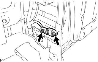
(a) Disconnect the connector from the rear airbag sensor.
NOTICE:
When disconnecting any airbag connector, take care not to damage the airbag wire harness.
(1) Push and hold the white housing lock, and slide the yellow outer connector locking sleeve.
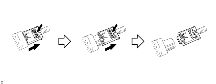
(2) Push and hold the white housing lock again, and slide the yellow outer connector locking sleeve to disconnect the connector.
(b) Remove the nut and the rear airbag sensor LH.
NOTICE:
Loosen the nut while holding the door side airbag sensor because the rear airbag sensor pin (stopper) is easily damaged.
 On-vehicle Inspection
ON-VEHICLE INSPECTION
PROCEDURE
1. INSPECT REAR AIRBAG SENSOR (for Vehicle not Involved in Collision)
(a) Perform a diagnostic system check (See page
).
2. INSPECT REAR AIRBAG SENSOR (for Vehicl ...

Other materials:
ECU Power Source Circuit
DESCRIPTION
This circuit supplies power to the millimeter wave radar sensor assembly when
the ignition switch is ON.
WIRING DIAGRAM
CAUTION / NOTICE / HINT
NOTICE:
Inspect the fuses for circuits related to this system before performing the following
inspection procedure.
PROCEDURE
...
Precaution
PRECAUTION
1. Check that the battery cables are connected to the correct terminals.
2. Disconnect the battery cables when the battery is given a quick charge.
3. Do not perform tests with a high voltage insulation resistance tester.
4. Never disconnect the battery while the engine is running.
5 ...
Precaution
PRECAUTION
1. IGNITION SWITCH EXPRESSIONS
(a) The type of ignition switch used on this model differs according to the specifications
of the vehicle. The expressions listed in the table below are used in this section.
Expression
Ignition Switch (Position)
Engine ...
