Toyota Tacoma (2015-2018) Service Manual: Door Unlock Detection Switch Circuit
DESCRIPTION
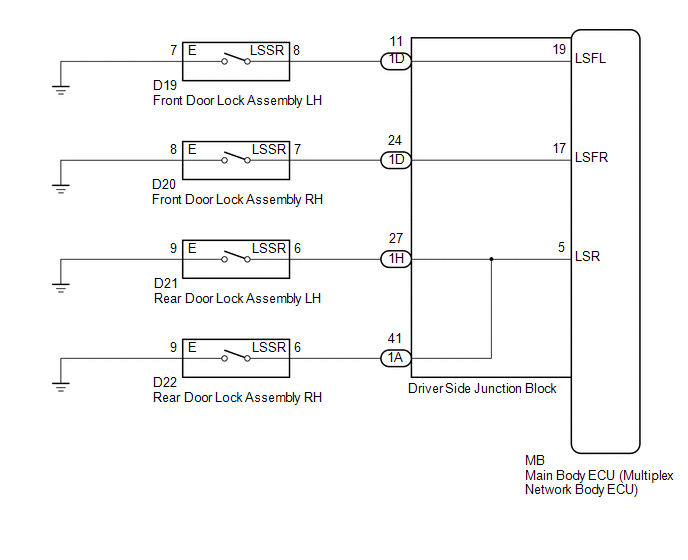
The main body ECU (multiplex network body ECU) detects the condition of each door unlock detection switch.
WIRING DIAGRAM
CAUTION / NOTICE / HINT
NOTICE:
If the main body ECU (multiplex network body ECU) is replaced, refer to Registration
(See page .gif) ).*1
).*1
- *1: w/ Smart Key System
PROCEDURE
|
1. |
READ VALUE USING TECHSTREAM (DOOR LOCK POS) |
(a) Connect the Techstream to the DLC3.
(b) Turn the ignition switch to ON.
(c) Turn the Techstream on.
(d) Enter the following menus: Body Electrical / Main Body / Data List.
(e) Read the Data List according to the display on the Techstream.
Main Body|
Tester Display |
Measurement Item/Range |
Normal Condition |
Diagnostic Note |
|---|---|---|---|
|
FR Door Lock Pos |
Front door RH unlock detection switch signal/LOCK or UNLOCK |
LOCK: Front door RH locked UNLOCK: Front door RH unlocked |
- |
|
FL Door Lock Pos |
Front door LH unlock detection switch signal/LOCK or UNLOCK |
LOCK: Front door LH locked UNLOCK: Front door LH unlocked |
- |
|
RR-Door Lock Pos SW |
Rear door RH unlock detection switch signal/ON or OFF |
ON: Rear door RH unlocked OFF: Rear door RH locked |
When checking this item, make sure to check it with the rear door LH locked. |
|
RL-Door Lock Pos SW |
Rear door LH unlock detection switch/ON or OFF |
ON: Rear door LH unlocked OFF: Rear door LH locked |
When checking this item, make sure to check it with the rear door RH locked. |
|
Result |
Proceed to |
|---|---|
|
OK |
A |
|
"FL Door Lock Pos" is not normal |
B |
|
"FR Door Lock Pos" is not normal |
C |
|
"RR-Door Lock Pos SW" is not normal |
D |
| A | .gif) |
PROCEED TO NEXT SUSPECTED AREA SHOWN IN PROBLEM SYMPTOMS TABLE |
| C | |
GO TO STEP 5 |
| D | |
GO TO STEP 8 |
|
.gif)
|
2. |
INSPECT FRONT DOOR LOCK ASSEMBLY LH |
(a) Remove the front door lock assembly LH.
(b) Inspect the front door lock assembly LH.
OK:
Front door lock assembly LH is normal.
| NG | |
REPLACE FRONT DOOR LOCK ASSEMBLY LH |
|
|
3. |
CHECK HARNESS AND CONNECTOR (FRONT DOOR LOCK ASSEMBLY LH - DRIVER SIDE JUNCTION BLOCK AND BODY GROUND) |
(a) Disconnect the 1D driver side junction block connector.
(b) Measure the resistance according to the value(s) in the table below.
Standard Resistance:
|
Tester Connection |
Condition |
Specified Condition |
|---|---|---|
|
D19-8 (LSSR) - 1D-11 |
Always |
Below 1 Ω |
|
D19-8 (LSSR) - Body ground |
Always |
10 kΩ or higher |
|
D19-7 (E) - Body ground |
Always |
Below 1 Ω |
| NG | |
REPAIR OR REPLACE HARNESS OR CONNECTOR |
|
|
4. |
INSPECT DRIVER SIDE JUNCTION BLOCK |
(a) Remove the driver side junction block (See page
).
(b) Remove the main body ECU (multiplex network body ECU) from the driver side junction block.
(c) Measure the resistance according to the value(s) in the table below.
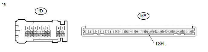 Text in Illustration
|
*a |
Component without harness connected (Driver Side Junction Block) |
- |
- |
Standard Resistance:
|
Tester Connection |
Condition |
Specified Condition |
|---|---|---|
|
1D-11 - MB-19 (LSFL) |
Always |
Below 1 Ω |
| NG | |
REPLACE DRIVER SIDE JUNCTION BLOCK |
|
|
5. |
INSPECT FRONT DOOR LOCK ASSEMBLY RH |
(a) Remove the front door lock assembly RH.
(b) Inspect the front door lock assembly RH.
OK:
Front door lock assembly RH is normal.
| NG | |
REPLACE FRONT DOOR LOCK ASSEMBLY RH |
|
|
6. |
CHECK HARNESS AND CONNECTOR (FRONT DOOR LOCK ASSEMBLY RH - DRIVER SIDE JUNCTION BLOCK AND BODY GROUND) |
(a) Disconnect the 1D driver side junction block connector.
(b) Measure the resistance according to the value(s) in the table below.
Standard Resistance:
|
Tester Connection |
Condition |
Specified Condition |
|---|---|---|
|
D20-7 (LSSR) - 1D-24 |
Always |
Below 1 Ω |
|
D20-7 (LSSR) - Body ground |
Always |
10 kΩ or higher |
|
D20-8 (E) - Body ground |
Always |
Below 1 Ω |
| NG | |
REPAIR OR REPLACE HARNESS OR CONNECTOR |
|
|
7. |
INSPECT DRIVER SIDE JUNCTION BLOCK |
(a) Remove the driver side junction block (See page
).
(b) Remove the main body ECU (multiplex network body ECU) from the driver side junction block.
(c) Measure the resistance according to the value(s) in the table below.
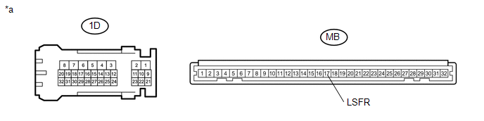 Text in Illustration
|
*a |
Component without harness connected (Driver Side Junction Block) |
- |
- |
Standard Resistance:
|
Tester Connection |
Condition |
Specified Condition |
|---|---|---|
|
1D-24 - MB-17 (LSFR) |
Always |
Below 1 Ω |
| NG | |
REPLACE DRIVER SIDE JUNCTION BLOCK |
|
|
8. |
INSPECT REAR DOOR LOCK ASSEMBLY LH |
(a) Remove the rear door lock assembly LH.
(b) Inspect the rear door lock assembly LH.
OK:
Rear door lock assembly LH is normal.
| NG | |
REPLACE REAR DOOR LOCK ASSEMBLY LH |
|
|
9. |
CHECK HARNESS AND CONNECTOR (REAR DOOR LOCK ASSEMBLY LH - DRIVER SIDE JUNCTION BLOCK AND BODY GROUND) |
(a) Disconnect the 1H driver side junction block connector.
(b) Measure the resistance according to the value(s) in the table below.
Standard Resistance:
|
Tester Connection |
Condition |
Specified Condition |
|---|---|---|
|
D21-6 (LSSR) - 1H-27 |
Always |
Below 1 Ω |
|
D21-6 (LSSR) - Body ground |
Always |
10 kΩ or higher |
|
D21-9 (E) - Body ground |
Always |
Below 1 Ω |
| NG | |
REPAIR OR REPLACE HARNESS OR CONNECTOR |
|
|
10. |
INSPECT REAR DOOR LOCK ASSEMBLY RH |
(a) Remove the rear door lock assembly RH.
(b) Inspect the rear door lock assembly RH.
OK:
Rear door lock assembly RH is normal.
| NG | |
REPLACE REAR DOOR LOCK ASSEMBLY RH |
|
|
11. |
CHECK HARNESS AND CONNECTOR (REAR DOOR LOCK ASSEMBLY RH - DRIVER SIDE JUNCTION BLOCK AND BODY GROUND) |
(a) Disconnect the 1A driver side junction block connector.
(b) Measure the resistance according to the value(s) in the table below.
Standard Resistance:
|
Tester Connection |
Condition |
Specified Condition |
|---|---|---|
|
D22-6 (LSSR) - 1A-41 |
Always |
Below 1 Ω |
|
D22-6 (LSSR) - Body ground |
Always |
10 kΩ or higher |
|
D22-9 (E) - Body ground |
Always |
Below 1 Ω |
| NG | |
REPAIR OR REPLACE HARNESS OR CONNECTOR |
|
|
12. |
INSPECT DRIVER SIDE JUNCTION BLOCK |
(a) Remove the driver side junction block (See page
).
(b) Remove the main body ECU (multiplex network body ECU) from the driver side junction block.
(c) Measure the resistance according to the value(s) in the table below.
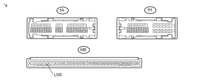 Text in Illustration
|
*a |
Component without harness connected (Driver Side Junction Block) |
- |
- |
Standard Resistance:
|
Tester Connection |
Condition |
Specified Condition |
|---|---|---|
|
1H-27 - MB-5 (LSR) |
Always |
Below 1 Ω |
|
1A-41 - MB-5 (LSR) |
Always |
Below 1 Ω |
| OK | |
REPLACE MAIN BODY ECU (MULTIPLEX NETWORK BODY ECU) |
| NG | |
REPLACE DRIVER SIDE JUNCTION BLOCK |
 Cargo Light Circuit
DESCRIPTION
The main body ECU (multiplex network body ECU) receives a cargo light information
signal from the deck light switch assembly and door courtesy light switch, and illuminates
the cargo ...
 High Beam Headlight Circuit
DESCRIPTION
The main body ECU (multiplex network body ECU) controls the high beam headlights.
WIRING DIAGRAM
CAUTION / NOTICE / HINT
NOTICE:
Inspect the fuses for circuits related to th ...
Other materials:
Problem Symptoms Table
PROBLEM SYMPTOMS TABLE
Use the table below to help determine the cause of problem symptoms.
If multiple suspected areas are listed, the potential causes of the symptoms
are listed in order of probability in the "Suspected Area" column of the
table. Check each symptom by ...
Terminals Of Ecu
TERMINALS OF ECU
1. OCCUPANT DETECTION ECU
Symbols (Terminal No.)
Wiring Color
Terminal Description
Condition
Specification
+B (O5-1) -
GND (O5-3)
R - W-B
Battery
Ignition switch on
...
Reassembly
REASSEMBLY
PROCEDURE
1. INSTALL INSTRUMENT PANEL CUSHION
(a) Install a new instrument panel cushion as shown in the illustration.
Text in Illustration
*a
R End
*b
25 to 45 mm
(0.984 to 1.772 in.)
...
