Toyota Tacoma (2015-2018) Service Manual: Removal
REMOVAL
CAUTION / NOTICE / HINT
HINT:
- Use the same procedure for both the RH and LH side.
- The procedure described below is for the LH side.
PROCEDURE
1. REMOVE REAR ACCESS PANEL WEATHERSTRIP
.gif)
2. REMOVE LAP BELT OUTER ANCHOR COVER
3. REMOVE ACCESS PANEL INSIDE HANDLE BEZEL
4. REMOVE DOOR PULL HANDLE
5. REMOVE REAR DOOR TRIM BOARD SUB-ASSEMBLY
6. REMOVE REAR DOOR GLASS SUB-ASSEMBLY
NOTICE:
The rear door glass sub-assembly may fall while performing this procedure. Therefore, use suction cups to hold the rear door glass sub-assembly from the outside of the vehicle.
|
(a) Apply protective tape to the area around the installation position of the rear door glass sub-assembly on the vehicle body to prevent it from being scratched. Text in Illustration
|
|
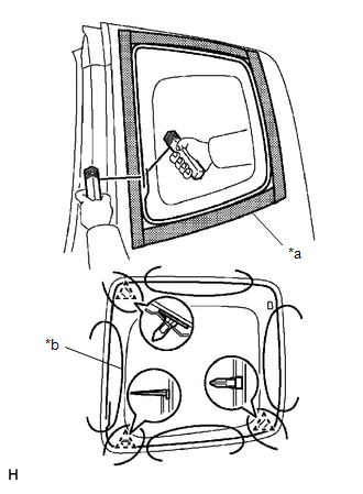
(b) Install the suction cups to the quarter window assembly.
(c) Pass a piano wire between the vehicle body and rear door glass sub-assembly from the interior.
(d) Tie objects that can serve as handles (for example, wooden blocks) to both wire ends.
(e) Cut off the adhesive by pulling the piano wire around the rear door glass sub-assembly.
(f) Using suction cups, disengage the 3 clips to remove the rear door glass sub-assembly.
 Components
COMPONENTS
ILLUSTRATION
...
 Installation
INSTALLATION
PROCEDURE
1. INSTALL REAR DOOR GLASS SUB-ASSEMBLY
(a) Clean and shape the contact surface of the vehicle body.
Text in Illustration
*a
...
Other materials:
Repair
REPAIR
PROCEDURE
1. REPAIR INTAKE VALVE SEATS
NOTICE:
Repair the intake valve seat while checking the seating position.
Keep the lip free of foreign matter.
(a) Using a 45° cutter, resurface the valve seat so that the valve seat
width is more than the specif ...
Installation
INSTALLATION
PROCEDURE
1. INSTALL REAR SEAT 3 POINT TYPE OUTER BELT ASSEMBLY
(a) Before installing the rear seat 3 point type outer belt assembly,
check the ELR function.
Text in Illustration
*a
Unlock
*b
...
Front Camera Module Circuit (C1AA0)
DESCRIPTION
The millimeter wave radar sensor assembly receives information about the area
in front of the vehicle from the forward recognition camera.
If the millimeter wave radar sensor assembly detects a malfunction in the forward
recognition camera, it will store DTC C1AA0.
DTC ...
