Toyota Tacoma (2015-2018) Service Manual: Replacement
REPLACEMENT
PROCEDURE
1. REPLACE STRAIGHT PIN
NOTICE:
It is not necessary to remove the straight pin unless it is being replaced.
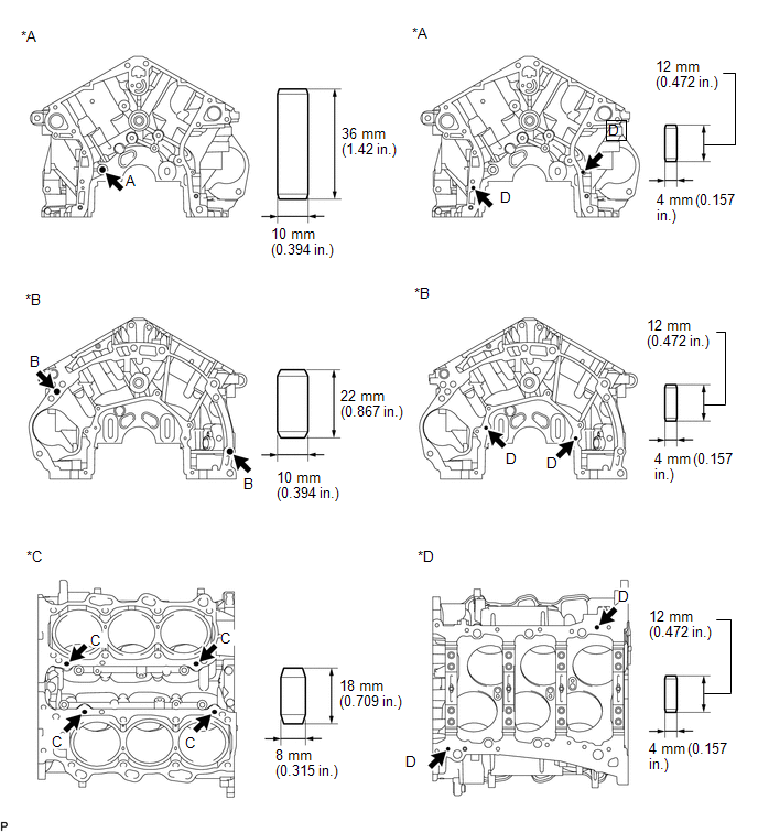
(a) Using a plastic-faced hammer, tap in new straight pins to the cylinder block.
 Text in Illustration
|
*A |
Front Side |
*B |
Rear Side |
|
*C |
Upper Side |
*D |
Lower Side |
Standard Protrusion:
|
Item |
Specified Condition |
|---|---|
|
Pin A |
22.5 to 23.5 mm (0.886 to 0.925 in.) |
|
Pin B |
10.5 to 11.5 mm (0.413 to 0.453 in.) |
|
Pin C |
8.5 to 9.5 mm (0.335 to 0.374 in.) |
|
Pin D |
5.5 to 6.5 mm (0.217 to 0.256 in.) |
2. REPLACE STUD BOLT
NOTICE:
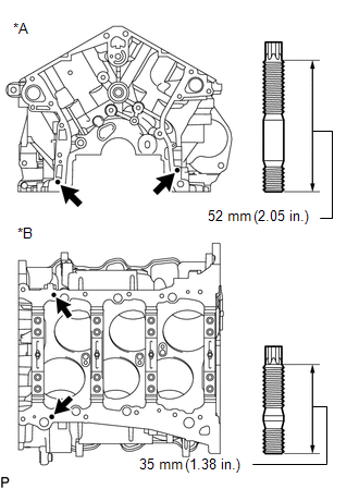
If a stud bolt is deformed or its threads are damaged, replace it.
|
(a) Using an E8 "TORX" socket wrench, install the stud bolts. Text in Illustration
Torque: 10 N┬Ěm {102 kgf┬Ěcm, 7 ft┬Ělbf} |
|
 Inspection
INSPECTION
PROCEDURE
1. INSPECT CYLINDER BLOCK FOR WARPAGE
(a) Using a precision straightedge and feeler gauge, measure the warpage
of the contact surface of the cylinder head gasket ...
 Cylinder Head
...
Other materials:
Removal
REMOVAL
CAUTION / NOTICE / HINT
NOTICE:
When replacing the windshield glass of a vehicle equipped with a forward recognition
camera, make sure to use a Toyota genuine part. If a non-Toyota genuine part is
used, the forward recognition camera may not be able to be installed due to a missing
...
Brake Switch "A" Circuit Open (P057113)
DESCRIPTION
When the brakes are applied by the dynamic radar cruise control system, the skid
control ECU (master cylinder solenoid)*1 or skid control ECU (brake actuator assembly)*2
operates the stop light switch assembly (stop light relay) to illuminate the stop
lights.
If the ECM receives ...
USB port/AUX port
Connect an iPod, USB memory device or portable audio player to the USB port/AUX
port as indicated below. Select ÔÇťiPodÔÇŁ, ÔÇťUSBÔÇŁ or ÔÇťAUXÔÇŁ on the ÔÇťSelect Audio SourceÔÇŁ
screen and the device can be operated via multimedia system.
Connecting using the USB port/AUX port
■ iPod
...
