Toyota Tacoma (2015-2018) Service Manual: Front Occupant Classification Sensor LH Circuit Malfunction (B1780)
DESCRIPTION
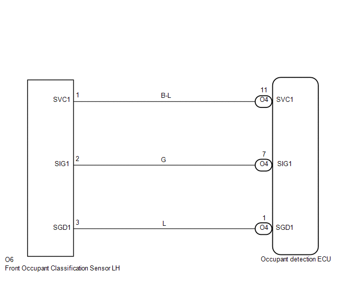
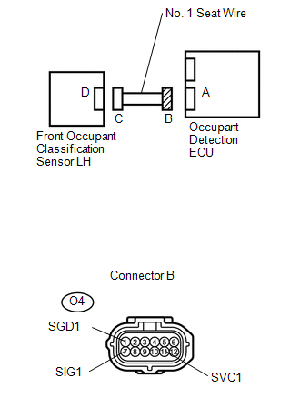
The occupant classification sensor front LH circuit consists of the occupant detection ECU and the occupant classification sensor front LH.
DTC B1780 is set when a malfunction is detected in the occupant classification sensor front LH circuit.
|
DTC No. |
DTC Detecting Conditions |
Trouble Areas |
|---|---|---|
|
B1780 |
|
|
HINT:
- When DTC B1650/32 is detected as a result of troubleshooting the supplemental restraint system, perform troubleshooting for DTC B1780 of the occupant classification system.
- Use the Techstream to check for DTCs of the occupant detection ECU, otherwise the DTC cannot be read.
WIRING DIAGRAM
CAUTION / NOTICE / HINT
HINT:
- If troubleshooting (wire harness inspection) is difficult to perform, remove the front RH seat assembly installation bolts to see the under surface of the seat cushion.
- In the above case, hold the seat so that it does not fall down. Holding the seat for a long period of time may cause problems, such as seat rail deformation. Hold the seat up only for as long as necessary.
PROCEDURE
|
1. |
CHECK DTC |
(a) Turn the ignition switch to the ON position.
(b) Clear any DTCs stored in the memory (See page
.gif) ).
).
HINT:
- First clear DTCs stored in the occupant detection ECU and then in the airbag sensor assembly.
- Use the Techstream to clear the DTCs of the occupant detection ECU, otherwise the DTCs cannot be cleared.
(c) Turn the ignition switch to the LOCK position.
(d) Turn the ignition switch to the ON position.
(e) Using the Techstream, check for DTCs of the occupant detection ECU (See page
).
OK:
DTC B1780 is not output.
HINT:
DTCs other than B1780 may be output at this time, but they are not related to this check.
| OK | .gif) |
PERFORM SENSITIVITY CHECK |
|
.gif)
|
2. |
CHECK CONNECTION OF CONNECTORS |
(a) Turn the ignition switch to the LOCK position.
(b) Disconnect the negative (-) terminal cable from the battery, and wait for at least 90 seconds.
(c) Check that the connectors are properly connected to the occupant detection ECU and the occupant classification sensor front LH.
OK:
The connectors are properly connected.
| NG | |
CONNECT CONNECTORS |
|
|
3. |
CHECK CONNECTORS |
(a) Check that the connectors (on the occupant detection ECU side and occupant
classification sensor front LH side) are not damaged (See page
).
OK:
The connectors are not deformed or damaged.
| NG | |
REPAIR OR REPLACE WIRE HARNESS |
|
|
4. |
CHECK NO. 1 SEAT WIRE (TO B+) |
|
(a) Disconnect the connectors from the occupant detection ECU and the occupant classification sensor front LH. |
|
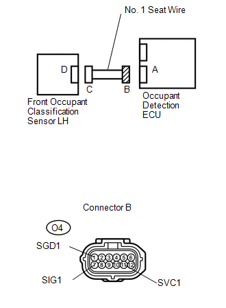
(b) Connect the negative (-) terminal cable to the battery.
(c) Turn the ignition switch to the ON position.
(d) Measure the voltage.
Standard voltage:
|
Tester Connection |
Condition |
Specified Condition |
|---|---|---|
|
O4-1 (SGD1) - Body ground |
Ignition switch ON |
Below 1 V |
|
O4-7 (SIG1) - Body ground |
Ignition switch ON |
Below 1 V |
|
O4-11 (SVC1) - Body ground |
Ignition switch ON |
Below 1 V |
| NG | |
REPAIR OR REPLACE NO. 1 SEAT WIRE |
|
|
5. |
CHECK NO. 1 SEAT WIRE (FOR OPEN) |
|
(a) Turn the ignition switch to the LOCK position. |
|
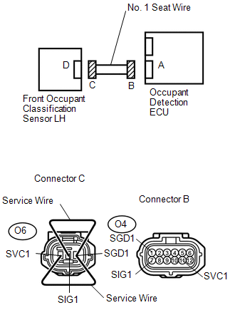
(b) Disconnect the negative (-) terminal cable from the battery, and wait for at least 90 seconds.
(c) Using service wires, connect O6-1 (SVC1) and O6-3 (SGD1), and connect O6-2 (SIG1) and O6-3 (SGD1) of connector C.
NOTICE:
Do not forcibly insert the service wires into the terminals of the connector when connecting.
(d) Measure the resistance.
Standard resistance:
|
Tester Connection |
Condition |
Specified Condition |
|---|---|---|
|
O4-7 (SIG1) - O4-1 (SGD1) |
Always |
Below 1 Ω |
|
O4-11 (SVC1) - O4-1 (SGD1) |
Always |
Below 1 Ω |
| NG | |
REPAIR OR REPLACE NO. 1 SEAT WIRE |
|
|
6. |
CHECK NO. 1 SEAT WIRE (FOR SHORT) |
|
(a) Disconnect the service wires from connector C. |
|
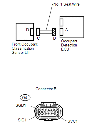
(b) Measure the resistance.
Standard resistance:
|
Tester Connection |
Condition |
Specified Condition |
|---|---|---|
|
O4-7 (SIG1) - O4-1 (SGD1) |
Always |
1 MΩ or higher |
|
O4-11 (SVC1) - O4-1 (SGD1) |
Always |
1 MΩ or higher |
|
O4-7 (SIG1) - O4-11 (SVC1) |
Always |
1 MΩ or higher |
| NG | |
REPAIR OR REPLACE NO. 1 SEAT WIRE |
|
|
7. |
CHECK NO. 1 SEAT WIRE (TO GROUND) |
(a) Measure the resistance.
Standard resistance:
|
Tester Connection |
Condition |
Specified Condition |
|---|---|---|
|
O4-1 (SGD1) - Body ground |
Always |
1 MΩ or higher |
|
O4-7 (SIG1) - Body ground |
Always |
1 MΩ or higher |
|
O4-11 (SVC1) - Body ground |
Always |
1 MΩ or higher |
| NG | |
REPAIR OR REPLACE NO. 1 SEAT WIRE |
|
|
8. |
CHECK DTC |
(a) Connect the connectors to the occupant detection ECU and the occupant classification sensor front LH.
(b) Connect the negative (-) terminal cable to the battery.
(c) Turn the ignition switch to the ON position.
(d) Clear any DTCs stored in the memory (See page
).
HINT:
- First clear DTCs stored in the occupant detection ECU and then in the airbag sensor assembly.
- Use the Techstream to clear the DTCs of the occupant detection ECU, otherwise the DTCs cannot be cleared.
(e) Turn the ignition switch to the LOCK position.
(f) Turn the ignition switch to the ON position.
(g) Using the Techstream, check for DTCs of the occupant detection ECU (See page
).
OK:
DTC B1780 is not output.
HINT:
DTCs other than B1780 may be output at this time, but they are not related to this check.
| OK | |
USE SIMULATION METHOD TO CHECK |
|
|
9. |
REPLACE OCCUPANT DETECTION ECU |
(a) Turn the ignition switch to the LOCK position.
(b) Disconnect the negative (-) terminal cable from the battery, and wait for at least 90 seconds.
(c) Replace the occupant detection ECU (See page
).
HINT:
Perform the inspection using parts from a normal vehicle when possible.
|
|
10. |
PERFORM ZERO POINT CALIBRATION |
(a) Connect the negative (-) terminal cable to the battery.
(b) Connect the Techstream to the DLC3.
(c) Turn the ignition switch to the ON position.
(d) Using the Techstream, perform the zero point calibration (See page
).
OK:
"Zero Point Calibration is complete." is displayed on the Techstream.
| NG | |
GO TO STEP 13 |
|
|
11. |
PERFORM SENSITIVITY CHECK |
(a) Using the Techstream, perform the sensitivity check (See page
).
Standard value:
27 to 33 kg (59.52 to 72.75 lb)
| NG | |
GO TO STEP 13 |
|
|
12. |
CHECK DTC |
(a) Connect the negative (-) terminal cable to the battery.
(b) Turn the ignition switch to the ON position.
(c) Clear any DTCs stored in the memory (See page
).
HINT:
- First clear DTCs stored in the occupant detection ECU and then in the airbag sensor assembly.
- Use the Techstream to clear the DTCs of the occupant detection ECU, otherwise the DTCs cannot be cleared.
(d) Turn the ignition switch to the LOCK position.
(e) Turn the ignition switch to the ON position.
(f) Using the Techstream, check for DTCs of the occupant detection ECU (See page
).
OK:
DTC B1780 is not output.
HINT:
DTCs other than B1780 may be output at this time, but they are not related to this check.
| OK | |
USE SIMULATION METHOD TO CHECK |
|
|
13. |
REPLACE FRONT SEAT WITH ADJUSTER FRAME ASSEMBLY RH |
(a) Turn the ignition switch to the LOCK position.
(b) Disconnect the negative (-) terminal cable from the battery, and wait for at least 90 seconds.
(c) Replace the front seat with adjuster frame assembly RH (See page
).
|
|
14. |
PERFORM ZERO POINT CALIBRATION |
(a) Connect the negative (-) terminal cable to the battery.
(b) Connect the Techstream to the DLC3.
(c) Turn the ignition switch to the ON position.
(d) Using the Techstream, perform the zero point calibration (See page
).
OK:
"Zero Point Calibration is complete." is displayed on the Techstream.
|
|
15. |
PERFORM SENSITIVITY CHECK |
(a) Using the Techstream, perform the sensitivity check (See page
).
Standard value:
27 to 33 kg (59.52 to 72.75 lb)
| NEXT | |
USE SIMULATION METHOD TO CHECK |
 Front Occupant Classification Sensor RH Circuit Malfunction (B1781)
DESCRIPTION
The front occupant classification sensor RH circuit consists of the occupant
detection ECU and the front occupant classification sensor RH.
DTC B1781 is set when a malfunction is detec ...

Other materials:
Test Mode Procedure
TEST MODE PROCEDURE
1. TEST MODE PROCEDURE (for Using Techstream)
HINT:
If the ignition switch is turned from the ON to the ACC or LOCK position
during test mode, DTCs related to the signal check function will be cleared.
During test mode, the skid control ECU (master cylinder ...
Problem Symptoms Table
PROBLEM SYMPTOMS TABLE
HINT:
Use the table below to help determine the cause of problem symptoms.
If multiple suspected areas are listed, the potential causes of the symptoms
are listed in order of probability in the "Suspected Area" column of the
table. Check each sy ...
Ecm
Components
COMPONENTS
ILLUSTRATION
ILLUSTRATION
Installation
INSTALLATION
PROCEDURE
1. INSTALL NO. 2 ECM BRACKET
(a) Install the No. 2 ECM bracket to the ECM with the 2 screws.
Torque:
3.2 N·m {33 kgf·cm, 28 in·lbf}
2. INSTALL ECM BRACKET
(a) Install the ECM bracket to the EC ...
