Toyota Tacoma (2015-2018) Service Manual: Front Differential Oil Temperature Sensor Circuit High (P17C8)
DESCRIPTION
This DTC is output when a short to B+ or open circuit in the oil temperature sensor is detected.
|
DTC No. |
Detection Item |
DTC Detection Condition |
Trouble Area |
|---|---|---|---|
|
P17C8 |
Front Differential Oil Temperature Sensor Circuit High |
|
|
WIRING DIAGRAM
Refer to DTC P17C7 (See page .gif) ).
).
PROCEDURE
|
1. |
CHECK OIL TEMPERATURE SENSOR |
(a) Disconnect the 4 wheel drive control ECU connector.
|
(b) Measure the resistance according to the value(s) in the table below. Standard Resistance:
|
|
(c) Measure the voltage according to the value(s) in the table below.
Standard Voltage:
|
Tester Connection |
Switch Condition |
Specified Condition |
|---|---|---|
|
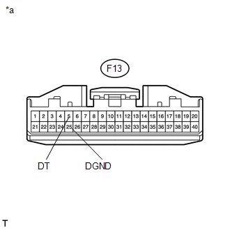
F13-5 (DT) or F13-25 (DGND) - Body ground |
Ignition switch ON |
Below 1 V |
|
*a |
Front view of wire harness connector (to 4 Wheel Drive Control ECU) |
| OK | .gif) |
REPLACE 4 WHEEL DRIVE CONTROL ECU |
|
.gif)
|
2. |
CHECK HARNESS AND CONNECTOR (4 WHEEL DRIVE CONTROL ECU - OIL TEMPERATURE SENSOR) |
(a) Disconnect the F13 4 wheel drive control ECU connector.
(b) Disconnect the F38 oil temperature sensor connector.
(c) Measure the resistance according to the value(s) in the table below.
Standard Resistance:
|
Tester Connection |
Condition |
Specified Condition |
|---|---|---|
|
F13-5 (DT) - F38-1 (DT) |
Always |
Below 1 Ω |
|
F13-25 (DGND) - F38-2 (DGND) |
Always |
Below 1 Ω |
(d) Measure the voltage according to the value(s) in the table below.
Standard Voltage:
|
Tester Connection |
Switch Condition |
Specified Condition |
|---|---|---|
|
F13-5 (DT) or F38-1 (DT) - Body ground |
Ignition switch ON |
Below 1 V |
|
F13-25 (DGND) or F38-2 (DGND) - Body ground |
Ignition switch ON |
Below 1 V |
| OK | |
REPLACE OIL TEMPERATURE SENSOR |
| NG | |
REPAIR OR REPLACE HARNESS OR CONNECTOR |
 Front Differential Oil Temperature Sensor Circuit Low (P17C7)
DESCRIPTION
This DTC is output when a short to ground in the oil temperature sensor is detected.
DTC No.
Detection Item
DTC Detection Condition
Trouble Ar ...
 Four Wheel Drive (4WD) Low Switch Circuit Range / Performance (P2772)
DESCRIPTION
This DTC is output when a malfunction in the L4 detection switch is detected.
DTC No.
Detection Item
DTC Detection Condition
Trouble Area
...
Other materials:
Installation
INSTALLATION
CAUTION / NOTICE / HINT
HINT:
Use the same procedure for the RH side and LH side.
The procedure listed below is for the LH side.
PROCEDURE
1. INSTALL FRONT COIL SPRING
(a) Install SST to the front coil spring, and secure SST in a vise.
SST: 09727-00 ...
Distance Control Switch Circuit
DESCRIPTION
The distance control switch is used to set the distance for vehicle-to-vehicle
distance control mode. The distance control switch is installed in the steering
pad switch assembly. The vehicle-to-vehicle distance set value can be changed by
operating the steering pad switch assembl ...
How To Proceed With Troubleshooting
CAUTION / NOTICE / HINT
HINT:
Use the following procedure to troubleshoot the air conditioning system.
*: Use the Techstream.
PROCEDURE
1.
VEHICLE BROUGHT TO WORKSHOP
NEXT
...
