Toyota Tacoma (2015-2018) Service Manual: Entry Exterior Alarm and Answer-back Buzzer do not Sound
DESCRIPTION
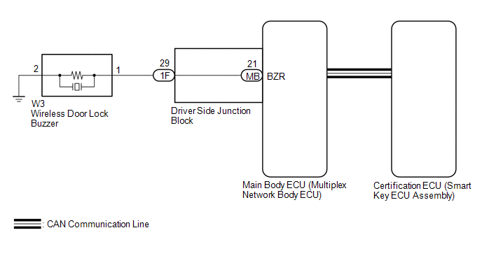
The smart key system (for Entry Function) uses the wireless door lock buzzer to perform various vehicle exterior warnings. When the conditions of each warning are met, the certification ECU (smart key ECU assembly) sends a buzzer activation request signal to the main body ECU (multiplex network body ECU) via CAN communication and the buzzer sounds.
WIRING DIAGRAM
CAUTION / NOTICE / HINT
NOTICE:
- The smart key system (for Entry Function) uses the LIN communication
system and CAN communication system. Inspect the communication function
by following How to Proceed with Troubleshooting. Troubleshoot the smart
key system (for Entry Function) after confirming that the communication
systems are functioning properly (See page
.gif) ).
). - When using the Techstream with the engine switch off, connect the Techstream to the DLC3 and turn a courtesy light switch on and off at intervals of 1.5 seconds or less until communication between the Techstream and the vehicle begins. Then select the vehicle type under manual mode and enter the following menus: Body Electrical / Smart Key. While using the Techstream, periodically turn a courtesy light switch on and off at intervals of 1.5 seconds or less to maintain communication between the Techstream and the vehicle.
- Before replacing the certification ECU (smart key ECU assembly) or main
body ECU (multiplex network body ECU), refer to smart key system (for Entry
Function) (See page ).
- After repair, confirm that no DTCs are output by performing "DTC Output Confirmation Operation".
PROCEDURE
|
1. |
CHECK CUSTOMIZE SETTING (WIRELESS BUZZER RESP) |
(a) Connect the Techstream to the DLC3.
(b) Turn the engine switch on (IG).
(c) Turn the Techstream on.
(d) Enter the following menus: Customize Setting / Wireless Door Lock.
Wireless Door Lock|
Tester Display |
Default |
Description |
Setting |
ECU |
|---|---|---|---|---|
|
Wireless Buzzer Resp |
ON |
Wireless buzzer response |
OFF or ON |
Main body ECU (multiplex network body ECU) |
|
Result |
Proceed to |
|---|---|
|
"ON" is displayed |
A |
|
"OFF" is displayed |
B |
| B | .gif) |
PERFORM CUSTOMIZE SETTING |
|
.gif)
|
2. |
CHECK WIRELESS DOOR LOCK CONTROL SYSTEM |
(a) Check that the wireless door lock functions operate normally (See page
).
|
Result |
Proceed to |
|---|---|
|
Wireless door lock function does not operate normally |
A |
|
Wireless door lock function operates normally |
B |
| B | |
GO TO PROBLEM SYMPTOMS TABLE |
|
|
3. |
READ VALUE USING TECHSTREAM (EACH UNLOCK DETECTION SWITCH) |
(a) Connect the Techstream to the DLC3.
(b) Turn the engine switch on (IG).
(c) Turn the Techstream on.
(d) Enter the following menus: Body Electrical / Main Body / Data List.
(e) Read the Data List according to the display on the Techstream.
Main Body|
Tester Display |
Measurement Item/Range |
Normal Condition |
Diagnostic Note |
|---|---|---|---|
|
FR Door Lock Pos |
Front door RH unlock detection switch signal / UNLOCK or LOCK |
UNLOCK: Front door RH unlocked LOCK: Front door RH locked |
- |
|
FL Door Lock Pos |
Front door LH unlock detection switch signal / UNLOCK or LOCK |
UNLOCK: Front door LH unlocked LOCK: Front door LH locked |
- |
|
RR-Door Lock Pos SW*1 |
Rear door RH unlock detection switch signal / ON or OFF |
ON: Rear door RH or LH unlocked OFF: Rear door RH and LH locked |
- |
|
RL-Door Lock Pos SW*1 |
Rear door LH unlock detection switch signal / ON or OFF |
ON: Rear door RH or LH unlocked OFF: Rear door RH and LH locked |
- |
- *1: for Double Cab
OK:
The Techstream display changes correctly in response to the lock/unlock operation.
| NG | |
GO TO LIGHTING SYSTEM (PROCEED TO DOOR UNLOCK DETECTION SWITCH CIRCUIT) |
|
|
4. |
PERFORM ACTIVE TEST USING TECHSTREAM (WIRELESS BUZZER) |
(a) Connect the Techstream to the DLC3.
(b) Turn the engine switch on (IG).
(c) Turn the Techstream on.
(d) Enter the following menus: Body Electrical / Main Body / Active Test.
(e) Perform Active Test according to the display on the Techstream.
Main Body|
Tester Display |
Measurement Item |
Control Range |
Diagnostic Note |
|---|---|---|---|
|
Wireless Buzzer |
Wireless door lock buzzer |
OFF/ON |
- |
|
Result |
Proceed to |
|---|---|
|
Wireless buzzer does not sound |
A |
|
Wireless buzzer sounds |
B |
| B | |
REPLACE CERTIFICATION ECU (SMART KEY ECU ASSEMBLY) |
|
|
5. |
INSPECT WIRELESS DOOR LOCK BUZZER |
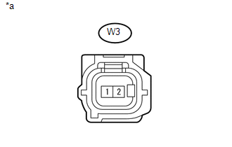
(a) Disconnect the wireless door lock buzzer connector.
(b) Perform the Active Test using the Techstream and sound the wireless door lock buzzer.
Main Body|
Tester Display |
Measurement Item |
Control Range |
Diagnostic Note |
|---|---|---|---|
|
Wireless Buzzer |
Wireless door lock buzzer |
OFF/ON |
- |
|
(c) While performing the Active Test, measure the voltage between the terminals of the wireless door lock buzzer. Standard Voltage:
|
|
| OK | |
REPLACE WIRELESS DOOR LOCK BUZZER |
|
|
6. |
CHECK HARNESS AND CONNECTOR (WIRELESS DOOR LOCK BUZZER - MAIN BODY ECU (MULTIPLEX NETWORK BODY ECU) AND BODY GROUND) |
(a) Remove the main body ECU (multiplex network body ECU) from the driver side
junction block (See page ).
(b) Reconnect the 1F driver side junction block connector.
(c) Measure the resistance according to the value(s) in the table below.
Standard Resistance:
|
Tester Connection |
Condition |
Specified Condition |
|---|---|---|
|
W3-1 - MB-21 (BZR) |
Always |
Below 1 Ω |
|
W3-2 - Body ground |
Always |
Below 1 Ω |
|
W3-1 or MB-21 (BZR) - Body ground |
Always |
10 kΩ or higher |
| OK | |
REPLACE MAIN BODY ECU (MULTIPLEX NETWORK BODY ECU) |
|
|
7. |
CHECK HARNESS AND CONNECTOR (WIRELESS DOOR LOCK BUZZER - DRIVER SIDE JUNCTION BLOCK) |
(a) Disconnect the 1F driver side junction block connector.
(b) Measure the resistance according to the value(s) in the table below.
Standard Resistance:
|
Tester Connection |
Condition |
Specified Condition |
|---|---|---|
|
W3-1 - 1F-29 |
Always |
Below 1 Ω |
|
W3-1 or 1F-29 - Body ground |
Always |
10 kΩ or higher |
| OK | |
REPLACE DRIVER SIDE JUNCTION BLOCK |
| NG | |
REPAIR OR REPLACE HARNESS OR CONNECTOR |
 New Key cannot be Registered
DESCRIPTION
If an electrical key transmitter could not be newly registered, wave interference
or a malfunction of the certification ECU (smart key ECU assembly), electrical key
transmitter sub-as ...
 Transmitter Battery(w/ Smart Key System)
Replacement
REPLACEMENT
CAUTION / NOTICE / HINT
NOTICE:
Take extra care when handling these precision electronic components.
PROCEDURE
1. REMOVE TRANSMITTER BATTERY
(a) Push the re ...
Other materials:
Key Cannot be Registered
DESCRIPTION
A maximum of 5 master key ID codes can be registered.
WIRING DIAGRAM
Refer to "B2780" (See page )
CAUTION / NOTICE / HINT
NOTICE:
If the transponder key ECU assembly is replaced, refer to Registration (See page
).
PROCEDURE
1.
CHECK REGISTRATIO ...
Reassembly
REASSEMBLY
CAUTION / NOTICE / HINT
NOTICE:
When installing, coat the parts indicated by the arrows with power steering fluid
(See page ).
PROCEDURE
1. INSTALL VANE PUMP HOUSING OIL SEAL
(a) Coat a new vane pump housing oil seal lip with power steering fluid.
(b) Using SST and a press, in ...
Removal
REMOVAL
CAUTION / NOTICE / HINT
HINT:
Use the same procedure for both the LH and RH sides.
The procedure described below is for the LH side.
PROCEDURE
1. REMOVE FRONT BUMPER ASSEMBLY
(See page
)
2. REMOVE HEADLIGHT ASSEMBLY
(a) Apply protective tape around the headlight ...
