Toyota Tacoma (2015-2018) Service Manual: On-vehicle Inspection
ON-VEHICLE INSPECTION
CAUTION / NOTICE / HINT
HINT:
Perform "Inspection After Repair" after replacing an ignition coil assembly or
spark plug (See page .gif) ).
).
PROCEDURE
1. PERFORM SPARK TEST
(a) Check for DTCs (See page ).
NOTICE:
If any DTC is output, perform the troubleshooting procedures for that DTC.
(b) Check if sparks occur.
(1) Remove the 6 spark plugs and 6 ignition coil assemblies (See page
).
(2) Install the spark plug to the ignition coil assembly and connect the ignition coil assembly connector.
(3) Remove the engine room relay block cover.
(4) Remove the EFI MAIN No. 2 relay (EFI MAIN NO. 2) from the engine room relay block.
(5) Ground the spark plug.
(6) Visually check that sparks occur while the engine is being cranked.
NOTICE:
- Be sure to ground the spark plug when checking.
- Replace the ignition coil assembly if it receives an impact.
- Do not crank the engine for more than 2 seconds.
2. INSPECT IGNITION COIL AND SPARK TEST
(a) Check that the wire harness side connector of the ignition coil assembly with igniter is securely connected.
Result|
Result |
Proceed to |
|---|---|
|
NG |
Connect securely |
|
OK |
Go to next step |
(b) Perform a spark test on each ignition coil assembly with igniter.
HINT:
Perform "Inspection After Repair" after replacing an ignition coil assembly (See
page ).
(1) If there is a cylinder where sparks do not occur, replace its ignition coil assembly with the ignition coil assembly of a cylinder where sparks occur normally.
(2) Crank the engine and visually check that sparks occur at the cylinder with the normally operating ignition coil assembly.
Result|
Result |
Proceed to |
|---|---|
|
OK |
Replace ignition coil assembly with igniter |
|
NG |
Go to next step |
(c) Inspect the spark plug.
HINT:
Perform "Inspection After Repair" after replacing an spark plug (See page
).
(1) Replace the spark plug with a normal one.
(2) Perform spark test again.
Result|
Result |
Proceed to |
|---|---|
|
OK |
Replace spark plug |
|
NG |
Go to next step |
(d) Check power supply to ignition coil assembly with igniter.
(1) Turn the engine switch to ON.
(2) Check that there is battery voltage at the ignition coil positive (+) terminal.
Result|
Result |
Proceed to |
|---|---|
|
NG |
Check wiring between engine switch and ignition coil assembly with igniter |
|
OK |
Go to next step |
(e) Install the 6 spark plugs and 6 ignition coil assemblies (See page
).
(f) Install the EFI MAIN No. 2 relay (EFI MAIN NO. 2) to the engine room relay block.
(g) Install the engine room relay block cover.
3. INSPECT SPARK PLUG
HINT:
Perform "Inspection After Repair" after replacing an spark plug (See page
).
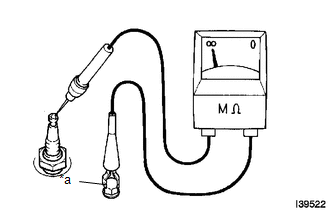
(a) Check the electrode.
|
(1) Using a megohmmeter, measure the insulation resistance. Text in Illustration
If a megohmmeter is not available, perform the following simple inspection. |
|
(b) Alternative inspection method:
(1) Quickly accelerate the engine to 4000 rpm 5 times.
(2) Remove the spark plug.
(3) Visually check the spark plug.
If the electrode is dry, the spark plug is functioning properly. If the electrode is damp, proceed to the next step.
(c) Check the spark plug for any damage on its threads and insulator.
HINT:
Perform "Inspection After Repair" after replacing an spark plug (See page
).
If there is damage, replace the spark plug. If not, reinstall the spark plug.
Recommended Spark Plug:
|
Manufacturer |
Product |
|---|---|
|
DENSO made |
FK20HBR8 |
NOTICE:
When replacing a spark plug, replace it with the same type of spark plug that is installed on the vehicle.
(d) Check the spark plug electrode gap.
Maximum electrode gap for used spark plug:
1.1 mm (0.0433 in.)
If the gap is more than the maximum, replace the spark plug.
Electrode gap for new spark plug:
0.7 to 0.8 mm (0.0276 to 0.0314 in.)
|
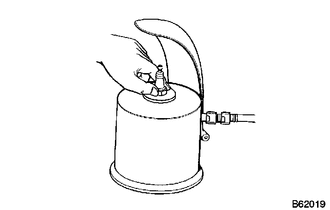
(e) Clean the spark plugs. If the electrode has traces of wet carbon, clean the electrode with a spark plug cleaner and then dry it. Air pressure: 588 kPa (6.0 kgf/cm2, 85 psi) Duration: 20 seconds or less HINT: Only use a spark plug cleaner when the electrode is free of oil. If the electrode has traces of oil, use gasoline to clean off the oil before using the spark plug cleaner. |
|
 System Diagram
SYSTEM DIAGRAM
...
 2gr-fks Intake
...
Other materials:
Operation Check
OPERATION CHECK
1. NOTICE WHEN CHECKING FOLLOWING
(a) Wireless door lock/unlock function:
This wireless door lock control function operates only when the following 3 conditions
are met:
(1) The engine switch is off.
(2) All doors are closed.
(3) The power door lock control system is operatin ...
Road Test
ROAD TEST
1. PROBLEM SYMPTOM CONFIRMATION
(a) Based on the result of the customer problem analysis, try to reproduce the
symptoms. If the problem is that the transmission does not shift up or down, or
that the shift point is too high or too low, conduct the following road test referring
to t ...
System Description
SYSTEM DESCRIPTION
1. SYSTEM DESCRIPTION
(a) The Electronic Controlled Automatic Transmission (ECT) is an automatic transmission
that has its shift timing electronically controlled by the ECM. The ECM detects
electrical signals that indicate engine and driving conditions, and controls the
sh ...
