Toyota Tacoma (2015-2018) Service Manual: Removal
REMOVAL
PROCEDURE
1. PRECAUTION
NOTICE:
After turning the ignition switch off, waiting time may be required before disconnecting the cable from the negative (-) battery terminal. Therefore, make sure to read the disconnecting the cable from the negative (-) battery terminal notices before proceeding with work.
Click here .gif)
2. DISCONNECT CABLE FROM NEGATIVE BATTERY TERMINAL
NOTICE:
When disconnecting the cable, some systems need to be initialized after the cable is reconnected.
Click here
3. REMOVE LOWER NO. 1 INSTRUMENT PANEL AIRBAG ASSEMBLY
Click here
4. SEPARATE MASTER CYLINDER PUSH ROD CLEVIS
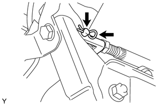
(a) Remove the clip and push rod pin, and then separate the push rod clevis.
5. REMOVE BRAKE PEDAL SUPPORT ASSEMBLY
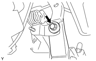
(a) Remove the bolt from the reinforcement.
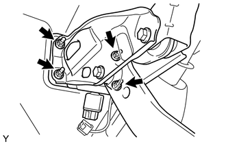
(b) Disconnect the stop light switch connector from the stop light switch.
|
(c) Remove the 4 nuts and brake pedal support. |
|
6. REMOVE BRAKE PEDAL PAD
(a) Remove the brake pedal pad from the brake pedal.
 On-vehicle Inspection
ON-VEHICLE INSPECTION
PROCEDURE
1. INSPECT BRAKE PEDAL HEIGHT
(a) Check the brake pedal height.
Pedal height from dash panel:
Type
Pedal Height
Automatic ...
 Installation
INSTALLATION
PROCEDURE
1. INSTALL BRAKE PEDAL PAD
(a) Install the brake pedal pad onto the brake pedal.
2. INSTALL BRAKE PEDAL SUPPORT ASSEMBLY
(a) Install the brake pedal support assembly with ...
Other materials:
Fail-safe Chart
FAIL-SAFE CHART
1. FAIL SAFE OPERATION
If there is a problem with any sensor signals or hydraulic brake booster
systems, the skid control ECU prohibits the power supply to the actuator
in the hydraulic brake booster and informs the ECM of VSC system failure.
The hydraulic brake b ...
Acceleration Sensor Internal Circuit (C1419,C1435)
DESCRIPTION
The skid control ECU (brake actuator assembly) receives signals from the yaw
rate and acceleration sensor (airbag sensor assembly) via the CAN communication
system.
The airbag sensor assembly has a built-in yaw rate and acceleration sensor and
detects the vehicle condition.
If t ...
Adjustment
ADJUSTMENT
PROCEDURE
1. BEFORE FILLING TRANSMISSION
The AC60E automatic transmission assembly requires Toyota Genuine ATF
WS.
If the entire automatic transmission assembly, automatic transmission
oil pan sub-assembly, drain plug, transmission valve body assembly and/or
torq ...
