Toyota Tacoma (2015-2018) Service Manual: Components
COMPONENTS
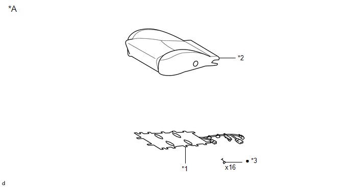
ILLUSTRATION
|
*A |
for Driver Side |
- |
- |
|
*1 |
FRONT SEAT CUSHION HEATER ASSEMBLY |
*2 |
SEPARATE TYPE FRONT SEAT CUSHION COVER |
|
*3 |
TAG PIN |
- |
- |
|
â—Ź |
Non-reusable part |
- |
- |
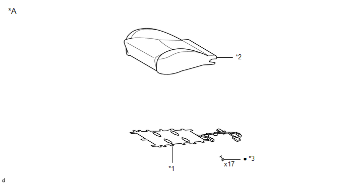
ILLUSTRATION
|
*A |
for Front Passenger Side |
- |
- |
|
*1 |
FRONT SEAT CUSHION HEATER ASSEMBLY |
*2 |
SEPARATE TYPE FRONT SEAT CUSHION COVER |
|
*3 |
TAG PIN |
- |
- |
|
â—Ź |
Non-reusable part |
- |
- |

 Inspection
INSPECTION
PROCEDURE
1. INSPECT FRONT SEAT CUSHION HEATER ASSEMBLY
(a) Check the operation of the front seat cushion heater assembly.
(1) Apply battery voltage and check the operation ...
Other materials:
VSC OFF Indicator Light does not Come ON
DESCRIPTION
Refer to VSC OFF Indicator Light Remains ON (See page
).
WIRING DIAGRAM
Refer to VSC OFF Indicator Light Remains ON (See page
).
CAUTION / NOTICE / HINT
NOTICE:
When replacing the skid control ECU (master cylinder solenoid), perform
calibration (See page
).
...
Diagnosis System
DIAGNOSIS SYSTEM
DIAGNOSIS FUNCTION
(a) The diagnosis function turns off the cruise control indicator, illuminates
the master warning light and displays a warning message when a malfunction is detected.
When a malfunction is detected in the dynamic radar cruise control system, DTCs
are store ...
Vehicle Information Not Obtained (C1A02)
DESCRIPTION
When a new millimeter wave radar sensor assembly is installed, it receives vehicle
specification information from the main body ECU (multiplex network body ECU) and
stores the information.
DTC C1A02 is stored when the millimeter wave radar sensor assembly receives the
vehicle spe ...
