Toyota Tacoma (2015-2018) Service Manual: VSC Buzzer Circuit
DESCRIPTION
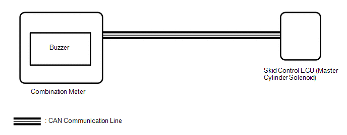
The skid control ECU (master cylinder solenoid) is connected to the combination meter via CAN communication.
The combination meter has a built-in VSC warning buzzer:
- Sounds intermittently to inform the driver if the temperature of hydraulic brake booster has increased excessively due to continuous operation of TRAC, A-TRAC and AUTO LSD.
- Sounds intermittently to inform the driver that the VSC is operating.
- Sounds continuously to alert the driver that the hydraulic pressure of accumulator in the hydraulic brake booster has decreased.
WIRING DIAGRAM
CAUTION / NOTICE / HINT
NOTICE:
When replacing the skid control ECU (master cylinder solenoid), perform the zero
point calibration (See page .gif) ).
).
PROCEDURE
|
1. |
CHECK CAN COMMUNICATION SYSTEM |
(a) Turn the ignition switch off.
(b) Connect the Techstream to the DLC3.
(c) Turn the ignition switch to ON.
(d) Turn the Techstream on.
(e) Select CAN Bus Check from the System Selection Menu screen and follow the
prompts on the screen to inspect the CAN bus (See page
).
OK:
CAN Bus Check indicates no malfunctions in CAN communication.
| NG | .gif) |
GO TO CAN COMMUNICATION SYSTEM (HOW TO PROCEED WITH TROUBLESHOOTING) |
|
.gif)
|
2. |
PERFORM ACTIVE TEST USING TECHSTREAM (BUZZER) |
(a) Connect the Techstream to the DLC3.
(b) Turn the ignition switch to ON.
(c) Turn the Techstream on.
(d) Enter the following menus: Chassis / ABS/VSC/TRAC / Active Test.
(e) According to the display on the tester, perform the Active Test.
ABS/VSC/TRAC|
Tester Display |
Test Part |
Control Range |
Diagnostic Note |
|---|---|---|---|
|
Buzzer |
VSC warning buzzer |
Buzzer OFF/ON |
The buzzer can be heard |
(f) Check that the buzzer sounds or stops in accordance with the Techstream.
Result|
Result |
Proceed to |
|---|---|
|
Buzzer does not sound or stop |
A |
|
Buzzer sounds and stops |
B |
| B | |
USE SIMULATION METHOD TO CHECK |
|
|
3. |
REPLACE COMBINATION METER ASSEMBLY |
(a) Turn the ignition switch off.
(b) Replace the combination meter (See page
).
|
|
4. |
PERFORM ACTIVE TEST USING TECHSTREAM (BUZZER) |
(a) Connect the Techstream to the DLC3.
(b) Turn the ignition switch to ON.
(c) Turn the Techstream on.
(d) Enter the following menus: Chassis / ABS/VSC/TRAC / Active Test.
(e) According to the display on the tester, perform the Active Test.
ABS/VSC/TRAC|
Tester Display |
Test Part |
Control Range |
Diagnostic Note |
|---|---|---|---|
|
Buzzer |
VSC warning buzzer |
Buzzer OFF/ON |
The buzzer can be heard |
(f) Check that the buzzer sounds or stops in accordance with the Techstream.
Result|
Result |
Proceed to |
|---|---|
|
Buzzer does not sound or stop |
A |
|
Buzzer sounds and stops |
B |
| A | |
REPLACE MASTER CYLINDER SOLENOID |
| B | |
END |
 A-TRAC Indicator Light Remains ON
DESCRIPTION
This is the A-TRAC main switch circuit. When the A-TRAC switch is turned on with
the transfer in L4, the A-TRAC function is available and the A-TRAC indicator light
illuminates.
WIRI ...

Other materials:
Blower Motor Circuit
DESCRIPTION
The blower motor with fan sub-assembly operates according to signals from the
air conditioning amplifier assembly. The blower motor with fan sub-assembly speed
signals are transmitted by changes in the duty ratio.
WIRING DIAGRAM
CAUTION / NOTICE / HINT
NOTICE:
Inspect the fuse ...
Clutch Accumulator
Components
COMPONENTS
ILLUSTRATION
Installation
INSTALLATION
PROCEDURE
1. INSTALL CLUTCH ACCUMULATOR ASSEMBLY
(a) Install the clutch accumulator assembly to the manual transmission assembly
with the 3 bolts.
Torque:
12 N·m {120 kgf·cm, 9 ft·lbf}
(b) Using a union nut wrench, co ...
Intake Air Control Valve Actuator(for Acis)
Components
COMPONENTS
ILLUSTRATION
Inspection
INSPECTION
PROCEDURE
1. INSPECT INTAKE AIR CONTROL VALVE ACTUATOR
(a) Check the operate.
(1) Apply battery voltage to the connector, and check the operation of
the intake air control valve actuator gear.
Text in Illustrati ...
