Toyota Tacoma (2015-2018) Service Manual: Driver Side Seat Heater does not Operate
DESCRIPTION
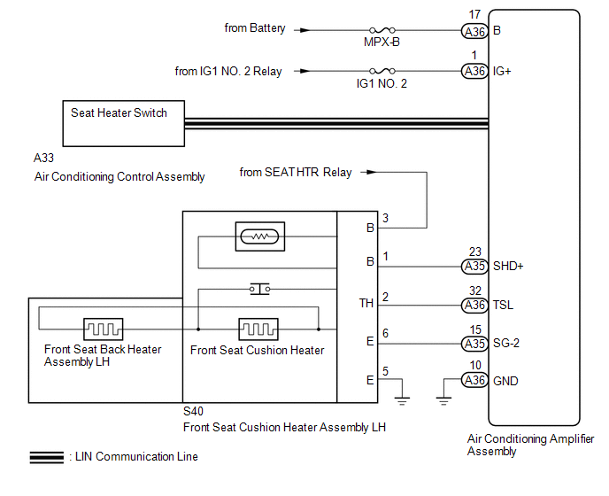
When the seat heater switch on the air conditioning control assembly is operated, the air conditioning amplifier assembly receives the signal. The air conditioning amplifier assembly receives the signal and operates the front seat heater.
WIRING DIAGRAM
CAUTION / NOTICE / HINT
NOTICE:
Inspect the fuses for circuits related to this system before performing the following inspection procedure.
PROCEDURE
|
1. |
READ VALUE USING TECHSTREAM |
(a) Connect the Techstream to the DLC3.
(b) Turn the ignition switch ON.
(c) Turn the Techstream on.
(d) Enter the following menus: Body Electrical / Air Conditioner / Data List.
(e) Check the value(s) by referring to the table below.
Air Conditioner:
|
Tester Display |
Measurement Item/Range |
Normal Condition |
Diagnostic Note |
|---|---|---|---|
|
FL Seat Heater Temperature |
Front seat LH side seat heater temperature / min: -29.7°C or max: 59.55°C |
Within range from 36 to 43°C (96 to 109°F) |
Front seat heater is on |
OK:
The display is as specified in the normal condition column.
Result|
Result |
Proceed to |
|---|---|
|
NG |
A |
|
OK |
B |
| B | .gif) |
REPLACE AIR CONDITIONING AMPLIFIER ASSEMBLY |
|
.gif)
|
2. |
CHECK HARNESS AND CONNECTOR (BATTERY - FRONT SEAT CUSHION HEATER ASSEMBLY LH - BODY GROUND) |
(a) Disconnect the S40 front seat cushion heater assembly LH connector.
(b) Measure the voltage and resistance according to the value(s) in the table below.
Standard Voltage:
|
Tester Connection |
Switch Condition |
Specified Condition |
|---|---|---|
|
S40-3 (B) - Body ground |
Ignition switch ON |
11 to 14 V |
Standard Resistance:
|
Tester Connection |
Condition |
Specified Condition |
|---|---|---|
|
S40-5 (E) - Body ground |
Always |
Below 1 Ω |
| NG | |
REPAIR OR REPLACE HARNESS OR CONNECTOR |
|
|
3. |
INSPECT FRONT SEAT CUSHION HEATER ASSEMBLY LH |
(a) Remove the front seat cushion heater assembly LH (See page
.gif) ).
).
(b) Inspect the front seat cushion heater assembly LH (See page
).
| NG | |
REPLACE FRONT SEAT CUSHION HEATER ASSEMBLY LH |
|
|
4. |
INSPECT FRONT SEATBACK HEATER ASSEMBLY LH |
(a) Remove the front seatback heater assembly LH (See page
).
(b) Inspect the front seatback heater assembly LH (See page
).
| NG | |
REPLACE FRONT SEATBACK HEATER ASSEMBLY LH |
|
|
5. |
CHECK FRONT SEAT CUSHION HEATER ASSEMBLY LH |
(a) Temporarily replace the front seat cushion heater assembly LH with a new
or known good one (See page
).
(b) Check that the seat heater system is operated normally.
OK:
The seat heater system is operated normally.
Result|
Result |
Proceed to |
|---|---|
|
NG |
A |
|
OK |
B |
| B | |
END (FRONT SEAT CUSHION HEATER ASSEMBLY LH WAS DEFECTIVE) |
|
|
6. |
CHECK HARNESS AND CONNECTOR (AIR CONDITIONING AMPLIFIER ASSEMBLY - FRONT SEAT CUSHION HEATER ASSEMBLY LH) |
(a) Disconnect the A35 and A36 air conditioning amplifier assembly connector.
(b) Disconnect the S40 front seat cushion heater assembly LH connector.
(c) Measure the resistance according to the value(s) in the table below.
Standard Resistance:
|
Tester Connection |
Condition |
Specified Condition |
|---|---|---|
|
A35-23 (SHD+) - S40-1 (B) |
Always |
Below 1 Ω |
|
A36-32 (TSL) - S40-2 (TH) |
Always |
Below 1 Ω |
|
A35-15 (SG-2) - S40-6 (E) |
Always |
Below 1 Ω |
|
A35-23 (SHD+) or S40-1 (B) |
Always |
10 kΩ or higher |
|
A36-32 (TSL) or S40-2 (TH) |
Always |
10 kΩ or higher |
|
A35-15 (SG-2) or S40-6 (E) |
Always |
10 kΩ or higher |
| NG | |
REPAIR OR REPLACE HARNESS OR CONNECTOR |
|
|
7. |
CHECK AIR CONDITIONING AMPLIFIER ASSEMBLY |
(a) Temporarily replace the air conditioning amplifier assembly with a new or
known good one (See page ).
(b) Check that the seat heater system is operated normally.
OK:
The seat heater system is operated normally.
Result|
Result |
Proceed to |
|---|---|
|
NG |
A |
|
OK |
B |
| A | |
END (AIR CONDITIONING AMPLIFIER ASSEMBLY WAS DEFECTIVE) |
| B | |
REPLACE AIR CONDITIONING AMPLIFIER ASSEMBLY |
 Front Left Seat Heat Sensor Circuit (B14C1)
DESCRIPTION
Output to the front seat cushion heater assembly LH temperature sensor stops
if one of the following occurs: 1) the temperature sensor is open or shorted; or
2) the temperature sensor ...
 Front Passenger Side Seat Heater does not Operate
DESCRIPTION
When the seat heater switch on the air conditioning control assembly is operated,
the air conditioning amplifier assembly receives the signal. The air conditioning
amplifier assembly ...
Other materials:
Engine Immobiliser System Malfunction (B2799,B279986)
DESCRIPTION
This DTC is stored when one of the following occurs: 1) the ECM detects errors
in its own communication with the transponder key ECU assembly; 2) the ECM detects
errors in the communication lines; or 3) the ECU communication ID between the transponder
key ECU assembly and ECM is d ...
Listening to an iPod
Connecting an iPod enables you to enjoy music from the vehicle speakers.
Select “iPod” on the “Select Audio Source” screen.
When the iPod connected to the system includes iPod video, the system can only
output the sound by selecting the browse screen.
Connecting an iPod
Audio control s ...
System Description
SYSTEM DESCRIPTION
1. DESCRIPTION
A part-time 2-speed VF2CM transfer uses a touch select 2-4 and high-low
system, enabling the driver to switch between 2WD, H4 and L4 modes by turning
the transfer position switch.
Through these switch signals, the 4 wheel drive control ECU actua ...
