Toyota Tacoma (2015-2018) Service Manual: Lost Communication with Meter (B1324)
DESCRIPTION
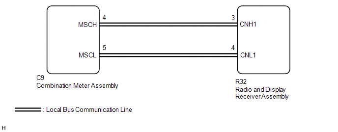
This DTC is stored when a communication error occurs between the radio and display receiver assembly and combination meter assembly.
|
DTC No. |
DTC Detection Condition |
Trouble Area |
|---|---|---|
|
B1324 |
After the radio and display receiver assembly receives a registration information signal, which is sent by the combination meter assembly when the ignition switch is turned to ACC, 1 or more times, the radio and display receiver assembly does not receive the signal for 30 seconds or more. |
|
WIRING DIAGRAM
PROCEDURE
|
1. |
CHECK HARNESS AND CONNECTOR (RADIO AND DISPLAY RECEIVER ASSEMBLY - COMBINATION METER ASSEMBLY) |
(a) Disconnect the R32 radio and display receiver assembly connector.
(b) Disconnect the C9 combination meter assembly connector.
(c) Measure the resistance according to the value(s) in the table below.
Standard Resistance:
|
Tester Connection |
Condition |
Specified Condition |
|---|---|---|
|
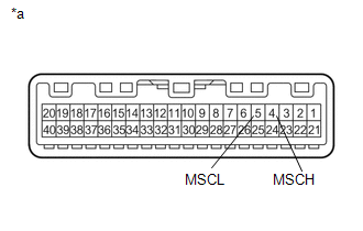
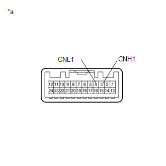
R32-3 (CNH1) - C9-4 (MSCH) |
Always |
Below 1 Ω |
|
R32-4 (CNL1) - C9-5 (MSCL) |
Always |
Below 1 Ω |
|
R32-3 (CNH1) - Body ground |
Always |
10 kΩ or higher |
|
R32-4 (CNL1) - Body ground |
Always |
10 kΩ or higher |
|
R32-3 (CNH1) - R32-4 (CNL1) |
Always |
10 kΩ or higher |
(d) Measure the voltage according to the value(s) in the table below.
Standard Voltage:
|
Tester Connection |
Condition |
Specified Condition |
|---|---|---|
|
R32-3 (CNH1) - Body ground |
Always |
Below 1 V |
|
R32-4 (CNL1) - Body ground |
Always |
Below 1 V |
| NG | .gif) |
REPAIR OR REPLACE HARNESS OR CONNECTOR |
|
.gif)
|
2. |
INSPECT COMBINATION METER ASSEMBLY |
(a) Remove the combination meter assembly (See page
.gif) ).
).
|
(b) Measure the resistance according to the value(s) in the table below. Standard Resistance:
|
|
| NG | |
REPLACE COMBINATION METER ASSEMBLY |
|
|
3. |
INSPECT RADIO AND DISPLAY RECEIVER ASSEMBLY |
(a) Remove the radio and display receiver assembly (See page
).
|
(b) Measure the resistance according to the value(s) in the table below. Standard Resistance:
|
|
| NG | |
REPLACE RADIO AND DISPLAY RECEIVER ASSEMBLY |
|
|
4. |
REPLACE COMBINATION METER ASSEMBLY |
(a) Replace the combination meter assembly with a new or known good one (See
page ).
(b) Clear the DTCs (See page ).
(c) Recheck for DTCs and check that no DTCs are output.
OK:
No DTCs are output.
| NG | |
REPLACE RADIO AND DISPLAY RECEIVER ASSEMBLY |
|
|
5. |
CHECK METER / GAUGE SYSTEM |
(a) Turn the ignition switch to ON and wait 30 seconds.
(b) Operate the steering pad switch assembly and check that the audio tab is displayed on the multi-information display in the combination meter assembly and the audio system can be operated normally.
OK:
Audio system returns to normal.
| OK | |
END |
| NG | |
REPLACE RADIO AND DISPLAY RECEIVER ASSEMBLY |
 Diagnostic Trouble Code Chart
DIAGNOSTIC TROUBLE CODE CHART
Audio and Visual System
DTC Code
Detection Item
See page
B1324
Lost Communication with Meter
...
 LVDS Signal Malfunction (from Extension Module) (B1532)
DESCRIPTION
The stereo component tuner assembly and the radio and display receiver assembly
are connected by an LVDS communication line.
This DTC is stored when an LVDS communication error occurs ...
Other materials:
Main Body ECU Vehicle Information Reading/Writing Process Malfunction (B15F6)
DESCRIPTION
This DTC is stored when items controlled by the main body ECU cannot be customized
via the navigation system vehicle customization screen.
HINT:
The main body ECU controls the items for the following systems that are customizable
via the navigation receiver assembly screen:
...
Operation Check
OPERATION CHECK
1. CHECK WIRELESS CHARGING SYSTEM OPERATION
(a) Turn the ignition switch ON (IG or ACC).
(b) Press the mobile wireless charger switch and check that the switch indicator
light illuminates.
Text in Illustration
*a
Switch Indicator Light
(c) Plac ...
Pressure Control Solenoid "B" Performance (Shift Solenoid Valve SL2) (P0776)
SYSTEM DESCRIPTION
The ECM uses the vehicle speed signal and signals from the transmission revolution
sensors (NT, SP2) to detect the actual gear (1st, 2nd, 3rd, 4th, 5th or 6th gear).
The ECM compares the actual gear with the shift schedule in the ECM memory to
detect mechanical problems of t ...
