Toyota Tacoma (2015-2018) Service Manual: Front Passenger Side Seat Heater does not Operate
DESCRIPTION
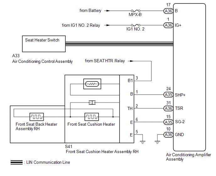
When the seat heater switch on the air conditioning control assembly is operated, the air conditioning amplifier assembly receives the signal. The air conditioning amplifier assembly receives the signal and operates the front seat heater.
WIRING DIAGRAM
CAUTION / NOTICE / HINT
NOTICE:
Inspect the fuses for circuits related to this system before performing the following inspection procedure.
PROCEDURE
|
1. |
READ VALUE USING TECHSTREAM |
(a) Connect the Techstream to the DLC3.
(b) Turn the ignition switch ON.
(c) Turn the Techstream on.
(d) Enter the following menus: Body Electrical / Air Conditioner / Data List.
(e) Check the value(s) by referring to the table below.
Air Conditioner:
|
Tester Display |
Measurement Item/Range |
Normal Condition |
Diagnostic Note |
|---|---|---|---|
|
FR Seat Heater Temperature |
Front seat RH side seat heater temperature / min: -29.7°C or max: 59.55°C |
Within range from 36 to 43°C (96 to 109°F) |
Front seat heater is on |
OK:
The display is as specified in the normal condition column.
Result|
Result |
Proceed to |
|---|---|
|
NG |
A |
|
OK |
B |
| B | .gif) |
REPLACE AIR CONDITIONING AMPLIFIER ASSEMBLY |
|
.gif)
|
2. |
CHECK HARNESS AND CONNECTOR (BATTERY - FRONT SEAT CUSHION HEATER ASSEMBLY RH - BODY GROUND) |
(a) Disconnect the S41 front seat cushion heater assembly RH connector.
(b) Measure the voltage and resistance according to the value(s) in the table below.
Standard Voltage:
|
Tester Connection |
Switch Condition |
Specified Condition |
|---|---|---|
|
S41-3 (B1) - Body ground |
Ignition switch ON |
11 to 14 V |
Standard Resistance:
|
Tester Connection |
Condition |
Specified Condition |
|---|---|---|
|
S41-5 (E) - Body ground |
Always |
Below 1 Ω |
| NG | |
REPAIR OR REPLACE HARNESS OR CONNECTOR |
|
|
3. |
INSPECT FRONT SEAT CUSHION HEATER ASSEMBLY RH |
(a) Remove the front seat cushion heater assembly RH (See page
.gif) ).
).
(b) Inspect the front seat cushion heater assembly RH (See page
).
| NG | |
REPLACE FRONT SEAT CUSHION HEATER ASSEMBLY RH |
|
|
4. |
INSPECT FRONT SEATBACK HEATER ASSEMBLY RH |
(a) Remove the front seatback heater assembly RH (See page
).
(b) Inspect the front seatback heater assembly RH (See page
).
| NG | |
REPLACE FRONT SEATBACK HEATER ASSEMBLY RH |
|
|
5. |
CHECK FRONT SEAT CUSHION HEATER ASSEMBLY RH |
(a) Temporarily replace the front seat cushion heater assembly RH with a new
or known good one (See page
).
(b) Check that the seat heater system is operated normally.
OK:
The seat heater system is operated normally.
Result|
Result |
Proceed to |
|---|---|
|
NG |
A |
|
OK |
B |
| B | |
END (FRONT SEAT CUSHION HEATER ASSEMBLY RH WAS DEFECTIVE) |
|
|
6. |
CHECK HARNESS AND CONNECTOR (AIR CONDITIONING AMPLIFIER ASSEMBLY - FRONT SEAT CUSHION HEATER ASSEMBLY RH) |
(a) Disconnect the A35 and A36 air conditioning amplifier assembly connector.
(b) Disconnect the S41 front seat cushion heater assembly RH connector.
(c) Measure the resistance according to the value(s) in the table below.
Standard Resistance:
|
Tester Connection |
Condition |
Specified Condition |
|---|---|---|
|
A35-24 (SHP+) - S41-1 (B) |
Always |
Below 1 Ω |
|
A36-31 (TSR) - S41-2 (TH) |
Always |
Below 1 Ω |
|
A35-15 (SG-2) - S41-6 (E) |
Always |
Below 1 Ω |
|
A35-24 (SHP+) or S41-1 (B) - Body ground |
Always |
10 kΩ or higher |
|
A36-31 (TSR) or S41-2 (TH) - Body ground |
Always |
10 kΩ or higher |
|
A35-15 (SG-2) or S41-6 (E) - Body ground |
Always |
10 kΩ or higher |
| NG | |
REPAIR OR REPLACE HARNESS OR CONNECTOR |
|
|
7. |
CHECK AIR CONDITIONING AMPLIFIER ASSEMBLY |
(a) Temporarily replace the air conditioning amplifier assembly with a new or
known good one (See page ).
(b) Check that the seat heater system is operated normally.
OK:
The seat heater system is operated normally.
Result|
Result |
Proceed to |
|---|---|
|
NG |
A |
|
OK |
B |
| A | |
END (AIR CONDITIONING AMPLIFIER ASSEMBLY WAS DEFECTIVE) |
| B | |
REPLACE AIR CONDITIONING AMPLIFIER ASSEMBLY |
 Driver Side Seat Heater does not Operate
DESCRIPTION
When the seat heater switch on the air conditioning control assembly is operated,
the air conditioning amplifier assembly receives the signal. The air conditioning
amplifier assembly ...
 Seat Belt
...
Other materials:
Installation
INSTALLATION
PROCEDURE
1. INSTALL TRANSMISSION FLOOR SHIFT ASSEMBLY
(a) Install the transmission floor shift assembly to the vehicle body with the
4 bolts.
Torque:
14 N·m {143 kgf·cm, 10 ft·lbf}
(b) Attach the 4 clamps to connect the wire harness to the transmission floor
shift assembl ...
Vehicle Control History
VEHICLE CONTROL HISTORY
1. Function Overview
(a) The vehicle control history is a function that records control data (record
data) when triggered by specific vehicle behavior. When DTCs are not detected according
to information provided by customers, by checking the vehicle control history, it ...
Diagnostic Trouble Code Chart
DIAGNOSTIC TROUBLE CODE CHART
NOTICE:
When removing any parts, turn the ignition switch off.
HINT:
If no abnormality is found when inspecting parts, check the skid control
ECU and check for poor contact at ground points.
When 2 or more DTCs are detected, perform each circuit insp ...
