Toyota Tacoma (2015-2018) Service Manual: Front Left Seat Heat Sensor Circuit (B14C1)
DESCRIPTION
Output to the front seat cushion heater assembly LH temperature sensor stops if one of the following occurs: 1) the temperature sensor is open or shorted; or 2) the temperature sensor is damaged and its output value does not change.
|
DTC Code |
DTC Detection Condition |
Trouble Area |
|---|---|---|
|
B14C1 |
Seat heater temperature sensor malfunction |
|
WIRING DIAGRAM
PROCEDURE
|
1. |
CLEAR DTC |
(a) Clear the DTCs (See page .gif) ).
).
|
.gif)
|
2. |
CHECK FOR DTC |
(a) Check for DTCs (See page ).
OK:
DTC B14C1 is not output.
| OK | .gif) |
USE SIMULATION METHOD TO CHECK |
|
|
3. |
READ VALUE USING TECHSTREAM |
(a) Connect the Techstream to the DLC3.
(b) Turn the ignition switch to ON.
(c) Turn the Techstream on.
(d) Enter the following menus: Body Electrical / Air Conditioner / Data List.
(e) Check the value(s) by referring to the table below.
Air Conditioner:
|
Tester Display |
Measurement Item/Range |
Normal Condition |
Diagnostic Note |
|---|---|---|---|
|
FL Seat Heater Temperature |
Front seat LH side seat heater temperature / min: -29.7°C or max: 59.55°C |
Within range from 36 to 42.2°C (96 to 108°F) |
Front seat heater is on |
OK:
The display is as specified in the normal condition column.
Result|
Result |
Proceed to |
|---|---|
|
NG |
A |
|
OK |
B |
| B | |
REPLACE AIR CONDITIONING AMPLIFIER ASSEMBLY |
|
|
4. |
INSPECT FRONT SEAT CUSHION HEATER ASSEMBLY LH |
(a) Remove the front seat cushion heater assembly LH (See page
).
(b) Inspect the front seat cushion heater assembly LH (See page
).
| NG | |
REPLACE FRONT SEAT CUSHION HEATER ASSEMBLY LH |
|
|
5. |
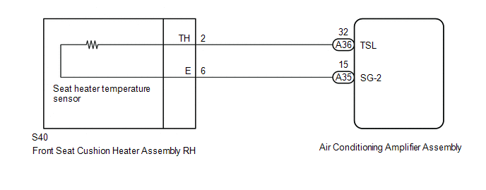
CHECK HARNESS AND CONNECTOR (AIR CONDITIONING AMPLIFIER ASSEMBLY - FRONT SEAT CUSHION HEATER ASSEMBLY LH) |
(a) Disconnect the A35 and A36 air conditioning amplifier assembly connector.
(b) Measure the resistance according to the value(s) in the table below.
Standard Resistance:
|
Tester Connection |
Condition |
Specified Condition |
|---|---|---|
|
A36-32 (TSL) - S40-2 (TH) |
Always |
Below 1 Ω |
|
A35-15 (SG-2) - S40-6 (E) |
Always |
Below 1 Ω |
|
A36-32 (TSL) - Body ground |
Always |
10 kΩ or higher |
|
A35-15 (SG-2) - Body ground |
Always |
10 kΩ or higher |
| OK | |
REPLACE AIR CONDITIONING AMPLIFIER ASSEMBLY |
| NG | |
REPAIR OR REPLACE HARNESS OR CONNECTOR |
 Front Right Seat Heat Sensor Circuit (B14C0)
DESCRIPTION
Output to the front seat cushion heater assembly RH temperature sensor stops
if one of the following occurs: 1) the temperature sensor is open or shorted; or
2) the temperature sensor ...
 Driver Side Seat Heater does not Operate
DESCRIPTION
When the seat heater switch on the air conditioning control assembly is operated,
the air conditioning amplifier assembly receives the signal. The air conditioning
amplifier assembly ...
Other materials:
Main Body ECU Communication Stop Mode
DESCRIPTION
Detection Item
Symptom
Trouble Area
Main Body ECU Communication Stop Mode
Either condition is met:
Communication stop for "Main Body" is indicated on the "Communication
Bus Check" screen ...
Room Oscillator does not Recognize Key
DESCRIPTION
If code verification cannot be performed in the vehicle interior, there may be
problems with the communication between the vehicle (indoor electrical key antenna
assembly (front floor) or (rear floor)) and electrical key transmitter sub-assembly,
or the certification ECU (smart ke ...
Reassembly
REASSEMBLY
PROCEDURE
1. INSTALL FRONT AXLE HUB OIL SEAL
(a) Using a brass bar and a hammer, install a new front axle hub oil seal.
NOTICE:
Do not damage the oil seal.
2. INSTALL FRONT AXLE WITH ABS ROTOR BEARING ASSEMBLY
(a) Using SST and a press, install a new bearing onto the front axle ...
