Toyota Tacoma (2015-2018) Service Manual: Inspection
INSPECTION
PROCEDURE
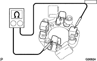
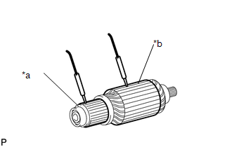
1. INSPECT MAGNET STARTER SWITCH ASSEMBLY
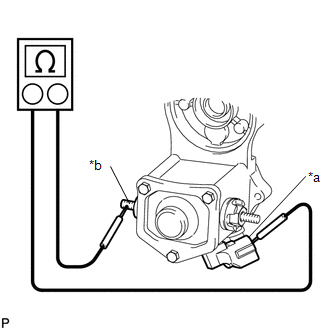
(a) Inspect the pull-in coil.
|
(1) Measure the resistance according to the value(s) in the table below. Text in Illustration
Standard Resistance:
If the result is not as specified, replace the magnet starter switch assembly. |
|
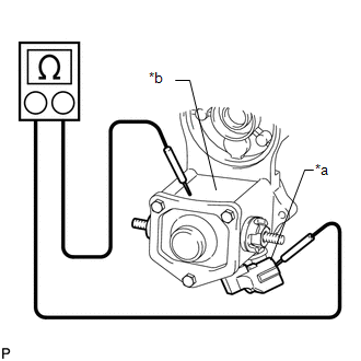
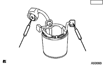
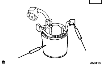
(b) Inspect the holding coil.
|
(1) Measure the resistance according to the value(s) in the table below. Text in Illustration
Standard Resistance:
If the result is not as specified, replace the magnet starter switch assembly. |
|
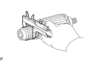
2. INSPECT BRUSH
|
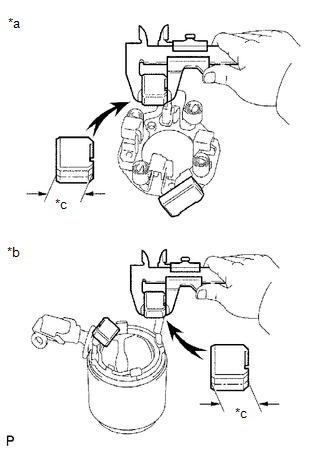
(a) Using a vernier caliper, measure the brush length. Text in Illustration
Standard length: 15.5 mm (0.610 in.) Minimum length: 8.5 mm (0.335 in.) If the length is less than the minimum, replace the starter brush holder assembly and starter yoke assembly. |
|
3. INSPECT STARTER BRUSH HOLDER ASSEMBLY
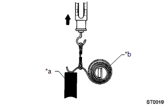
(a) Check the brush spring load.
|
(1) Take a pull scale reading immediately after the brush spring separates from the brush. Text in Illustration
Standard spring load: 17.6 to 23.5 N (1.8 to 2.4 kgf, 4.0 to 5.3 lbf) Minimum spring load: 11.8 N (1 kgf, 2.7 lbf) If the spring load is less than the minimum, replace the starter brush holder assembly. |
|
(b) Inspect the insulation.
|
(1) Measure the resistance according to the value(s) in the table below. Standard Resistance:
If the result is not as specified, replace the starter brush holder assembly. |
|
4. INSPECT STARTER YOKE ASSEMBLY
(a) Inspect the field coil for an open circuit.
|
(1) Measure the resistance according to the value(s) in the table below. Standard Resistance:
If the result is not as specified, replace the starter yoke assembly. |
|
|
(2) Measure the resistance according to the value(s) in the table below. Standard Resistance:
If the result is not as specified, replace the starter yoke assembly. |
|
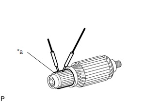
5. INSPECT STARTER ARMATURE ASSEMBLY
(a) Check the commutator for dirt and/or burns on the surface.
If the surface is dirty or burnt, correct it with sandpaper (No. 400) or a lathe. If necessary, replace the starter armature assembly.
(b) Inspect the commutator for an open circuit.
|
(1) Measure the resistance according to the value(s) in the table below. Text in Illustration
Standard Resistance:
If the result is not as specified, replace the starter armature assembly. |
|
(c) Inspect the commutator for a short circuit.
|
(1) Measure the resistance according to the value(s) in the table below. Text in Illustration
Standard Resistance:
If the result is not as specified, replace the starter armature assembly. |
|
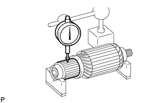
(d) Check the commutator circle runout.
(1) Place the bearing of armature on V-blocks.
|
(2) Using a dial indicator, measure the circle runout. Maximum runout: 0.05 mm (0.00197 in.) If the circle runout is more than the maximum, replace the starter armature assembly. |
|
|
(e) Using a vernier caliper, measure the commutator diameter. Standard diameter: 30.0 mm (1.18 in.) Minimum diameter: 29.0 mm (1.14 in.) If the diameter is less than the minimum, replace the starter armature assembly. |
|
|
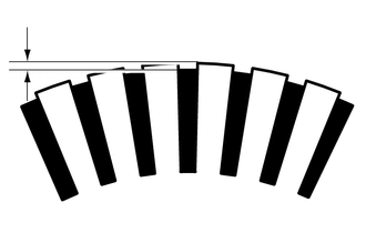
(f) Using a vernier caliper, measure the undercut depth of the commutator. Standard undercut depth: 0.6 mm (0.0236 in.) Minimum undercut depth: 0.2 mm (0.00787 in.) If the undercut depth is less than the minimum, replace the starter armature assembly. |
|
6. INSPECT STARTER CLUTCH SUB-ASSEMBLY
(a) Rotate the pinion gear clockwise and check that it turns freely. Try to rotate the pinion gear counterclockwise and check that it locks.
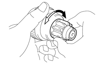 Text in Illustration
.png) |
Free |
.png) |
Lock |
If the result is not as specified, replace the starter clutch sub-assembly.
(b) Turn the pinion gear by hand while applying inward force and check the movement of the bearing.
If resistance is felt or the bearing sticks, replace the starter clutch sub-assembly.
 Disassembly
DISASSEMBLY
PROCEDURE
1. REMOVE STARTER YOKE ASSEMBLY
(a) Remove the nut and disconnect the lead wire from terminal C.
(b) Remove the 2 bolts.
...
 Removal
REMOVAL
PROCEDURE
1. PRECAUTION
NOTICE:
After turning the engine switch off, waiting time may be required before disconnecting
the cable from the battery terminal. Therefore, make sure to read t ...
Other materials:
Installation
INSTALLATION
CAUTION / NOTICE / HINT
HINT:
Use the same procedure for both the RH and LH sides.
The procedure described below is for the LH side.
PROCEDURE
1. INSTALL FRONT SHOULDER BELT ANCHOR ADJUSTER ASSEMBLY
(a) As shown in the illustration, engage the 2 guides ...
Turn Signal Switch Circuit
DESCRIPTION
The combination meter assembly receives the turn signal switch information and
controls the turn signal lights.
WIRING DIAGRAM
PROCEDURE
1.
READ VALUE USING TECHSTREAM (TURN SIGNAL SWITCH)
(a) Connect the Techstream to the DLC3.
(b) Turn the igni ...
Data List / Active Test
DATA LIST / ACTIVE TEST
1. DATA LIST
HINT:
Using the Techstream to read the Data List allows the values or states of switches,
sensors, actuators and other items to be read without removing any parts. This non-intrusive
inspection can be very useful because intermittent conditions or signals ...
