Toyota Tacoma (2015-2018) Service Manual: Cruise Control Main Switch
Components
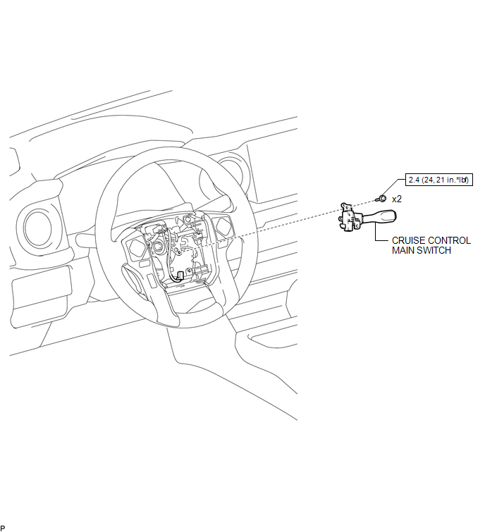
COMPONENTS
ILLUSTRATION
Removal
REMOVAL
PROCEDURE
1. REMOVE STEERING PAD ASSEMBLY
(See page .gif) )
)
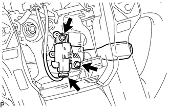
2. REMOVE CRUISE CONTROL MAIN SWITCH
|
(a) Disconnect the connector and remove the 2 screws. |
|
|
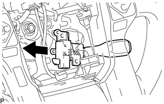
(b) Remove the cruise control main switch from the steering wheel. |
|
Installation
INSTALLATION
PROCEDURE
1. INSTALL CRUISE CONTROL MAIN SWITCH
|
(a) Install the cruise control main switch with the 2 screws and connect the connector. Torque: 2.4 N·m {24 kgf·cm, 21 in·lbf} |
|
.png)
2. INSTALL STEERING PAD ASSEMBLY
(See page .gif) )
)
 Clutch Switch
Components
COMPONENTS
ILLUSTRATION
Removal
REMOVAL
PROCEDURE
1. PRECAUTION
NOTICE:
After turning the engine switch off, waiting time may be required before disconnecting
the cable from ...

Other materials:
Door Unlock Detection Switch Circuit
DESCRIPTION
The main body ECU (multiplex network body ECU) detects the condition of each
door unlock detection switch.
WIRING DIAGRAM
CAUTION / NOTICE / HINT
NOTICE:
If the main body ECU (multiplex network body ECU) is replaced, refer to Registration
(See page ).*1
*1: w/ Smart K ...
Repair
REPAIR
PROCEDURE
1. STEERING OFF CENTER REPAIR PROCEDURE
(a) Check if the steering wheel is off center.
(1) Apply masking tape to the top center of the steering wheel and upper
steering column cover.
Text in Illustration
*1
Steering Wheel
...
New Key cannot be Registered
DESCRIPTION
If an electrical key transmitter could not be newly registered, wave interference
or a malfunction of the certification ECU (smart key ECU assembly), electrical key
transmitter sub-assembly, steering lock ECU (steering lock actuator or UPR bracket
assembly) or electrical key and T ...
