Toyota Tacoma (2015-2018) Service Manual: Door Courtesy Switch Circuit
DESCRIPTION
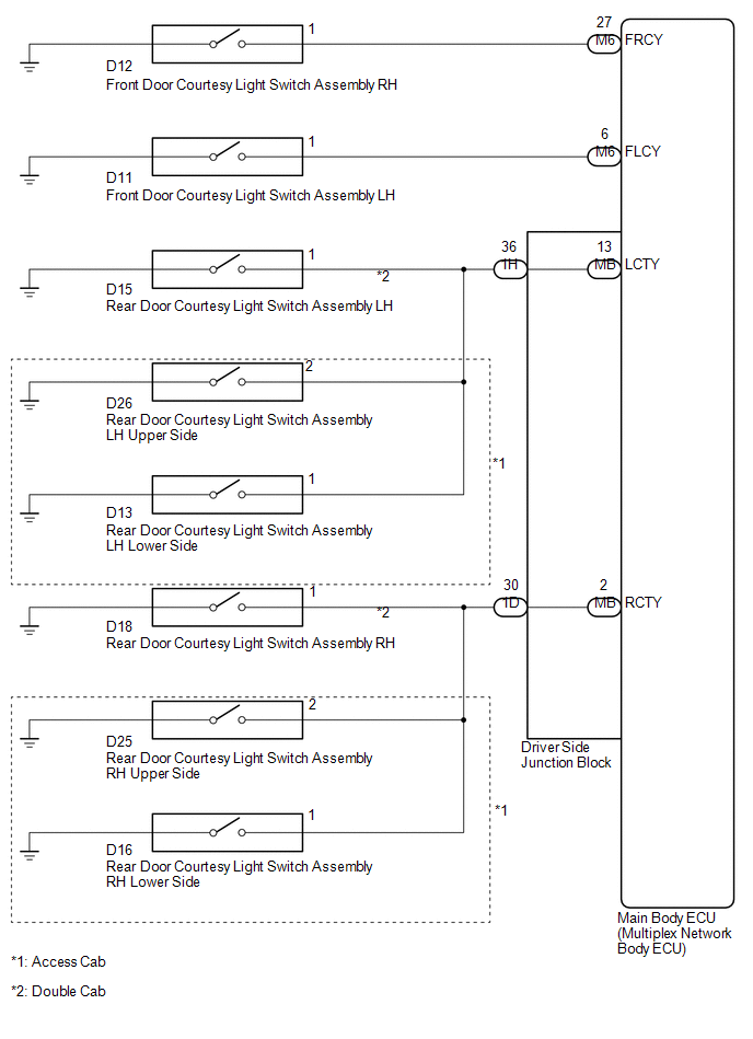
The main body ECU (multiplex network Body ECU) receives a door open or closed signal from each door courtesy light switch.
WIRING DIAGRAM
CAUTION / NOTICE / HINT
NOTICE:
- Recognition code registration is necessary when replacing the main body ECU (multiplex network body ECU).
- If the main body ECU (multiplex network body ECU) is replaced, refer
to Registration (See page
.gif) ).*1
).*1
- *1: w/ Smart Key System
PROCEDURE
|
1. |
READ VALUE USING TECHSTREAM (DOOR COURTESY LIGHT SWITCH) |
(a) Connect the Techstream to the DLC3.
(b) Turn the ignition switch to ON.
(c) Turn the Techstream on.
(d) Enter the following menus: Body Electrical / Main Body / Data List.
(e) According to the display on the Techstream, read the Data List.
Main Body|
Tester Display |
Measurement Item/Range |
Normal Condition |
Diagnostic Note |
|---|---|---|---|
|
RR Door Courtesy SW |
Rear door courtesy light switch RH signal / ON or OFF |
ON: Rear door RH open OFF: Rear door RH closed |
- |
|
RL Door Courtesy SW |
Rear door courtesy light switch LH signal / ON or OFF |
ON: Rear door LH open OFF: Rear door LH closed |
- |
|
FR Door Courtesy |
Front door courtesy light switch RH signal / ON or OFF |
ON: Front door RH closed OFF: Front door RH open |
- |
|
FL Door Courtesy |
Front door courtesy light switch LH signal / ON or OFF |
ON: Front door LH closed OFF: Front door LH open |
- |
OK:
Normal conditions listed above are displayed.
Result|
Result |
Proceed to |
|---|---|
|
OK |
A |
|
NG (Rear door courtesy light switch RH does not operate) |
B |
|
NG (Rear door courtesy light switch LH does not operate) |
C |
|
NG (Front door courtesy light switch RH does not operate) |
D |
|
NG (Front door courtesy light switch LH does not operate) |
E |
| A | .gif) |
PROCEED TO NEXT SUSPECTED AREA SHOWN IN PROBLEM SYMPTOMS TABLE |
| C | |
GO TO STEP 5 |
| D | |
GO TO STEP 8 |
| E | |
GO TO STEP 10 |
|
.gif)
|
2. |
INSPECT REAR DOOR COURTESY LIGHT SWITCH RH |
(a) for Double Cab
(1) Remove the rear door courtesy light switch RH.
(2) Inspect the rear door courtesy light switch RH (See page
).
(b) for Access Cab
(1) Remove the rear door courtesy light switch RH upper side.
(2) Remove the rear door courtesy light switch RH lower side.
(3) Inspect the rear door courtesy light switch RH upper side (See page
).
(4) Inspect the rear door courtesy light switch RH lower side (See page
).
|
Result |
Proceed to |
|---|---|
|
OK |
A |
|
NG (for Double Cab) |
B |
|
NG (for Access Cab) |
C |
| B | |
REPLACE REAR DOOR COURTESY LIGHT SWITCH RH |
| C | |
REPLACE REAR DOOR COURTESY LIGHT SWITCH RH |
|
|
3. |
CHECK HARNESS AND CONNECTOR (REAR DOOR COURTESY LIGHT SWITCH RH - DRIVER SIDE JUNCTION BLOCK) |
(a) for Double Cab
(1) Disconnect the D18 rear door courtesy light switch RH connector.
(2) Disconnect the 1D driver side junction block connector.
(3) Measure the resistance according to the value(s) in the table below.
Standard Resistance:
|
Tester Connection |
Condition |
Specified Condition |
|---|---|---|
|
D18-1 - 1D-30 |
Always |
Below 1 Ω |
|
D18-1 - Body ground |
Always |
10 kΩ or higher |
(b) for Access Cab
(1) Disconnect the D16 and D25 rear door courtesy light switch RH connector.
(2) Disconnect the 1D driver side junction block connector.
(3) Measure the resistance according to the value(s) in the table below.
Standard Resistance:
|
Tester Connection |
Condition |
Specified Condition |
|---|---|---|
|
D16-1 - 1D-30 |
Always |
Below 1 Ω |
|
D16-1 - Body ground |
Always |
10 kΩ or higher |
|
D25-2 - 1D-30 |
Always |
Below 1 Ω |
|
D25-2 - Body ground |
Always |
10 kΩ or higher |
| NG | |
REPAIR OR REPLACE HARNESS OR CONNECTOR |
|
|
4. |
INSPECT DRIVER SIDE JUNCTION BLOCK |
|
(a) Remove the driver side junction block (See page
|
|
(b) Remove the main body ECU (multiplex network body ECU) from the driver side
junction block (See page ).
(c) Measure the resistance according to the value(s) in the table below.
Standard Resistance:
|
Tester Connection |
Condition |
Specified Condition |
|---|---|---|
|
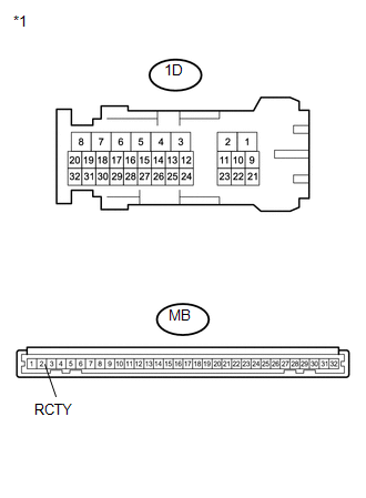
MB-2 (RCTY) - 1D-30 |
Always |
Below 1 Ω |
|
*1 |
Component without harness connected (Driver Side Junction Block) |
| OK | |
REPLACE MAIN BODY ECU (MULTIPLEX NETWORK BODY ECU) |
| NG | |
REPLACE DRIVER SIDE JUNCTION BLOCK |
|
5. |
INSPECT REAR DOOR COURTESY LIGHT SWITCH LH |
(a) for Double Cab
(1) Remove the rear door courtesy light switch LH.
(2) Inspect the rear door courtesy light switch LH (See page
).
(b) for Access Cab
(1) Remove the rear door courtesy light switch LH upper side.
(2) Remove the rear door courtesy light switch LH lower side.
(3) Inspect the rear door courtesy light switch LH upper side (See page
).
(4) Inspect the rear door courtesy light switch LH lower side (See page
).
|
Result |
Proceed to |
|---|---|
|
OK |
A |
|
NG (for Double Cab) |
B |
|
NG (for Access Cab) |
C |
| B | |
REPLACE REAR DOOR COURTESY LIGHT SWITCH LH |
| C | |
REPLACE REAR DOOR COURTESY LIGHT SWITCH LH |
|
|
6. |
CHECK HARNESS AND CONNECTOR (REAR DOOR COURTESY LIGHT SWITCH LH - DRIVER SIDE JUNCTION BLOCK) |
(a) for Double Cab
(1) Disconnect the D15 rear door courtesy light switch LH connector.
(2) Disconnect the 1H driver side junction block connector.
(3) Measure the resistance according to the value(s) in the table below.
Standard Resistance:
|
Tester Connection |
Condition |
Specified Condition |
|---|---|---|
|
D15-1 - 1H-36 |
Always |
Below 1 Ω |
|
D15-1 - Body ground |
Always |
10 kΩ or higher |
(b) for Access Cab
(1) Disconnect the D13 and D26 rear door courtesy light switch LH connector.
(2) Disconnect the 1H driver side junction block connector.
(3) Measure the resistance according to the value(s) in the table below.
Standard Resistance:
|
Tester Connection |
Condition |
Specified Condition |
|---|---|---|
|
D13-1 - 1H-36 |
Always |
Below 1 Ω |
|
D13-1 - Body ground |
Always |
10 kΩ or higher |
|
D26-2 - 1H-36 |
Always |
Below 1 Ω |
|
D26-2 - Body ground |
Always |
10 kΩ or higher |
| NG | |
REPAIR OR REPLACE HARNESS OR CONNECTOR |
|
|
7. |
INSPECT DRIVER SIDE JUNCTION BLOCK |
|
(a) Remove the driver side junction block (See page
|
|
(b) Remove the main body ECU (multiplex network body ECU) from the driver side
junction block (See page ).
(c) Measure the resistance according to the value(s) in the table below.
Standard Resistance:
|
Tester Connection |
Condition |
Specified Condition |
|---|---|---|
|
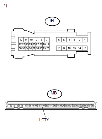
MB-13 (LCTY) - 1H-36 |
Always |
Below 1 Ω |
|
*1 |
Component without harness connected (Driver Side Junction Block) |
| OK | |
REPLACE MAIN BODY ECU (MULTIPLEX NETWORK BODY ECU) |
| NG | |
REPLACE DRIVER SIDE JUNCTION BLOCK |
|
8. |
INSPECT FRONT DOOR COURTESY LIGHT SWITCH RH |
(a) Remove the front door courtesy light switch RH.
(b) Inspect the front door courtesy light switch RH (See page
).
| NG | |
REPLACE FRONT DOOR COURTESY LIGHT SWITCH RH |
|
|
9. |
CHECK HARNESS AND CONNECTOR (FRONT DOOR COURTESY LIGHT SWITCH RH - MAIN BODY ECU (MULTIPLEX NETWORK BODY ECU)) |
(a) Disconnect the D12 front door courtesy light switch RH connector.
(b) Disconnect the M6 main body ECU (multiplex network body ECU) connector.
(c) Measure the resistance according to the value(s) in the table below.
Standard Resistance:
|
Tester Connection |
Condition |
Specified Condition |
|---|---|---|
|
D12-1 - M6-27 (FRCY) |
Always |
Below 1 Ω |
|
D12-1 - Body ground |
Always |
10 kΩ or higher |
| OK | |
REPLACE MAIN BODY ECU (MULTIPLEX NETWORK BODY ECU) |
| NG | |
REPAIR OR REPLACE HARNESS OR CONNECTOR |
|
10. |
INSPECT FRONT DOOR COURTESY LIGHT SWITCH LH |
(a) Remove the front door courtesy light switch LH.
(b) Inspect the front door courtesy light switch LH (See page
).
| NG | |
REPLACE FRONT DOOR COURTESY LIGHT SWITCH LH |
|
|
11. |
CHECK HARNESS AND CONNECTOR (FRONT DOOR COURTESY LIGHT SWITCH LH - MAIN BODY ECU (MULTIPLEX NETWORK BODY ECU)) |
(a) Disconnect the D11 front door courtesy light switch LH connector.
(b) Disconnect the M6 main body ECU (multiplex network body ECU) connector.
(c) Measure the resistance according to the value(s) in the table below.
Standard Resistance:
|
Tester Connection |
Condition |
Specified Condition |
|---|---|---|
|
D11-1 - M6-6 (FLCY) |
Always |
Below 1 Ω |
|
D11-1 - Body ground |
Always |
10 kΩ or higher |
| OK | |
REPLACE MAIN BODY ECU (MULTIPLEX NETWORK BODY ECU) |
| NG | |
REPAIR OR REPLACE HARNESS OR CONNECTOR |
 Headlight Dimmer Switch Circuit
DESCRIPTION
The main body ECU (multiplex network body ECU) receives the following switch
information:
Light control switch position is off (DRL OFF), tail, head or AUTO (DRL).
Dimmer ...
 Front Fog Light Circuit
DESCRIPTION
The main body ECU (multiplex network body ECU) controls the front fog lights.
WIRING DIAGRAM
CAUTION / NOTICE / HINT
NOTICE:
Inspect the fuses for circuits related to this s ...
Other materials:
Center Airbag Sensor Assembly Malfunction (B1000/31)
DESCRIPTION
The airbag sensor assembly consists of a deceleration sensor, safing sensor,
drive circuit, diagnosis circuit, ignition control, etc.
If the airbag sensor assembly receives signals from the deceleration sensor,
it determines whether or not the SRS should be activated.
DTC B1000/31 ...
Installation
INSTALLATION
PROCEDURE
1. INSTALL TRANSFER POSITION SWITCH
(a) Attach the 2 claws to install the transfer position switch.
2. INSTALL AIR CONDITIONING CONTROL ASSEMBLY (for Automatic Air Conditioning
System)
(See page )
3. INSTALL INTEGRATION PANEL SUB-ASSEMBLY (for Manual Cooler System)
...
Short in Curtain Shield Squib RH Circuit (B1830/57-B1833/57)
DESCRIPTION
The front passenger side curtain shield squib circuit consists of the airbag
sensor assembly and the curtain shield airbag assembly RH.
The circuit signals the SRS to deploy when airbag deployment conditions are met.
These DTCs are set when a malfunction is detected in the front pas ...
