Toyota Tacoma (2015-2018) Service Manual: Inspection
INSPECTION
PROCEDURE
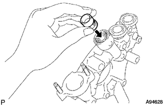
1. INSPECT OIL PUMP RELIEF VALVE
|
(a) Coat the oil pump relief valve with engine oil and check that it falls smoothly into the valve hole by its own weight. If the valve does not fall smoothly, replace the timing chain cover assembly. |
|
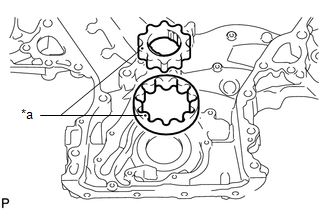
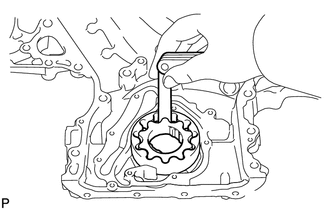
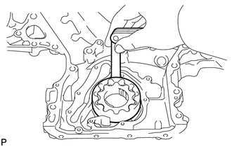
2. INSPECT OIL PUMP ROTOR SET
|
(a) Place the drive and driven rotors into the timing chain cover with the marks facing upward. Text in Illustration
|
|
(b) Check the rotor tip clearance.
|
(1) Using a feeler gauge, measure the clearance between the drive and driven rotor tips. Standard tip clearance: 0.06 to 0.16 mm (0.00236 to 0.00630 in.) Maximum tip clearance: 0.16 mm (0.00630 in.) If the clearance is more than the maximum, replace the drive and driven rotors as a set. |
|
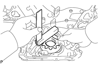
(c) Check the rotor side clearance.
|
(1) Using a feeler gauge and steel square, measure the clearance between the rotors and precision straightedge. Standard side clearance: 0.030 to 0.075 mm (0.00118 to 0.00295 in.) Maximum side clearance: 0.075 mm (0.00295 in.) If the clearance is more than the maximum, replace the drive and driven rotors as a set. If necessary, replace the timing chain cover assembly. |
|
(d) Check the rotor body clearance.
|
(1) Using a feeler gauge, measure the clearance between the driven rotor and body. Standard body clearance: 0.250 to 0.325 mm (0.00984 to 0.0128 in.) Maximum body clearance: 0.325 mm (0.0128 in.) If the clearance is more than the maximum, replace the drive and driven rotors as a set. If necessary, replace the timing chain cover assembly. |
|
 Disassembly
DISASSEMBLY
PROCEDURE
1. REMOVE OIL PUMP RELIEF VALVE
(a) Using a 27 mm socket wrench, remove the oil pump relief valve plug.
(b) Remove the oil pump relief valve spring and oil pump re ...
 Removal
REMOVAL
PROCEDURE
1. REMOVE ENGINE ASSEMBLY
(See page )
2. REMOVE IGNITION COIL ASSEMBLY
3. REMOVE ENGINE OIL LEVEL DIPSTICK GUIDE
4. REMOVE CAMSHAFT TIMING OIL CONTROL SOLENOID ASSEMBLY ...
Other materials:
System Diagram
SYSTEM DIAGRAM
HINT:
Each tire pressure warning valve and transmitter sends its transmitter ID, temperature
and tire pressure information to the tire pressure warning ECU and receiver.
Transmitting ECU (Transmitter)
Receiving ECU
Signal
Communicat ...
AVC-LAN Circuit
DESCRIPTION
Each unit of the navigation system connected to the AVC-LAN (communication bus)
transfers the switch signals using the AVC-LAN.
If a short to +B or short to ground occurs in the AVC-LAN, the navigation system
will not function normally because communication is not possible.
WIRING ...
Installation
INSTALLATION
CAUTION / NOTICE / HINT
NOTICE:
Always use a new grommet and valve core when installing the tire pressure
warning valve and transmitter.
Check that the washer and nut are not damaged, and replace them if necessary.
If installing a new tire pressure warning valv ...
