Toyota Tacoma (2015-2018) Service Manual: Disassembly
DISASSEMBLY
PROCEDURE
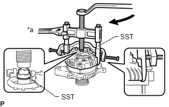
1. REMOVE GENERATOR PULLEY
(a) Mount the generator assembly in the vise between aluminum plates.
NOTICE:
Do not overtighten the vise.
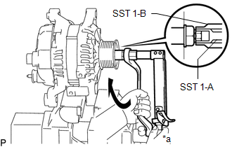
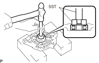
(b) Install SST 1-A to the generator pulley shaft.
 Text in Illustration
|
*a |
Hold |
.png) |
Turn |
SST: 09820-63011
09820-06010
09820-06021
(c) Install SST 1-B to SST 1-A.
(d) Hold SST 1-A with a torque wrench and turn SST 1-B clockwise with the specified torque.
Torque:
39 N·m {398 kgf·cm, 29 ft·lbf}
NOTICE:
Make sure that SST is secured to the generator rotor shaft.
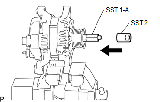
(e) Insert SST 2 and attach it to the generator pulley nut.
 Text in Illustration
|
|
Insert |
SST: 09820-63011
09820-06010
09820-06021
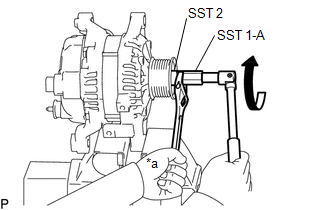
(f) To loosen the generator pulley nut, turn SST 1-A as shown in the illustration.
 Text in Illustration
|
*a |
Hold |
|
|
Turn |
NOTICE:
To prevent damage to the generator rotor shaft, do not loosen the generator pulley nut more than one-self of a turn.
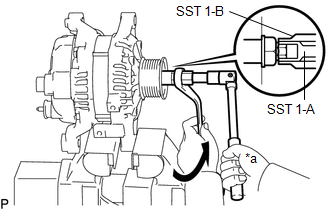
(g) Remove SST 2 from the generator pulley shaft.
(h) Turn SST 1-B as shown in the illustration and remove SST 1-A and B.
 Text in Illustration
|
*a |
Hold |
|
|
Turn |
(i) Remove the pulley nut and generator pulley.
(j) Remove the generator assembly from the vise.
2. REMOVE GENERATOR REAR END COVER
|
(a) Place the generator assembly on the generator pulley. |
|
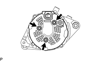
(b) Remove the 3 bolts and generator rear end cover from the generator coil assembly.
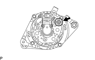
3. REMOVE TERMINAL INSULATOR
|
(a) Remove the terminal insulator from the generator coil assembly. |
|
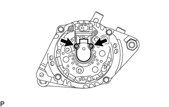
4. REMOVE GENERATOR BRUSH HOLDER ASSEMBLY
|
(a) Remove the 2 screws and generator brush holder assembly from the generator coil assembly. |
|
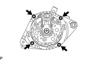
5. REMOVE GENERATOR COIL ASSEMBLY
|
(a) Remove the 4 through bolts. |
|
(b) Using SST, remove the generator coil assembly.
 Text in Illustration
|
*a |
Hold |
|
|
Turn |
SST: 09950-40011
09951-04020
09952-04010
09953-04020
09954-04010
09955-04071
09957-04010
09958-04011
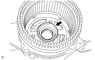
6. REMOVE GENERATOR BEARING COVER PACKING
|
(a) Remove the generator bearing cover packing. NOTICE: If the generator bearing cover packing breaks, remove all broken pieces. HINT: The generator bearing cover packing may be installed on the generator rotor assembly. |
|
7. REMOVE GENERATOR ROTOR ASSEMBLY
(a) Remove the generator rotor assembly from the generator drive end frame.
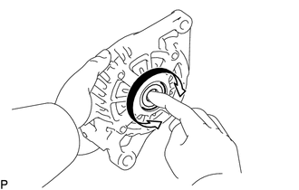
8. INSPECT GENERATOR DRIVE END FRAME BEARING
|
(a) Check that the generator drive end frame bearing is not rough or worn and that it rotates smoothly. If necessary, replace the generator drive end frame bearing. |
|
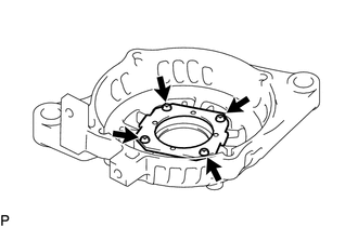
9. REMOVE GENERATOR DRIVE END FRAME BEARING
|
(a) Remove the 4 screws and retainer plate from the generator drive end frame. |
|
|
(b) Using SST and a hammer, tap out the generator drive end frame bearing from the generator drive end frame. SST: 09950-60010 09951-00250 SST: 09950-70010 09951-07100 |
|
 Removal
REMOVAL
PROCEDURE
1. PRECAUTION
NOTICE:
After turning the ignition switch off, waiting time may be required before disconnecting
the cable from the negative (-) battery terminal. Therefore, make ...
 Inspection
INSPECTION
PROCEDURE
1. INSPECT GENERATOR BRUSH HOLDER ASSEMBLY
(a) Using a vernier caliper, measure the brush length.
Text in Illustration
*a
Len ...
Other materials:
Removal
REMOVAL
PROCEDURE
1. PLACE FRONT WHEELS FACING STRAIGHT AHEAD
2. REMOVE FRONT WHEELS
3. REMOVE FRONT UPPER FENDER APRON SEAL
Click here
4. REMOVE NO. 2 ENGINE UNDER COVER SUB-ASSEMBLY (w/ Off Road Package)
5. REMOVE NO. 1 ENGINE UNDER COVER SUB-ASSEMBLY
6. REMOVE FRONT DIFFERENTIAL CARRI ...
AUTO LSD Indicator Light Remains ON
DESCRIPTION
During normal mode, pressing the VSC OFF switch for a short amount of time changes
vehicle to AUTO LSD mode.
WIRING DIAGRAM
CAUTION / NOTICE / HINT
NOTICE:
When replacing the skid control ECU (master cylinder solenoid), perform
calibration (See page
).
Inspe ...
Dtc Check / Clear
DTC CHECK / CLEAR
1. DTC CHECK USING TECHSTREAM
(a) Connect the Techstream to the DLC3.
(b) Turn the ignition switch to ON.
(c) Turn the Techstream on.
(d) Enter the following menus: Body Electrical / Air Conditioner / Trouble Codes.
(e) Check for DTCs.
2. DTC CLEAR USING TECHSTREAM
(a) Conn ...
