Toyota Tacoma (2015-2018) Service Manual: Dtc Check / Clear
DTC CHECK / CLEAR
1. CHECK DTC (CHECK USING TECHSTREAM)
(a) Connect the Techstream to the DLC3.
(b) Turn the ignition switch to ON.
(c) Turn the Techstream on.
(d) Enter the following menus: Body Electrical / Navigation System / Trouble Codes.
(e) Check for DTCs, and then write them down.
(f) Check the details of the DTC(s) (See page .gif) ).
).
NOTICE:
The audio and visual system outputs DTCs for the following system. When DTCs other than those in Diagnostic Trouble Code Chart for the audio and visual system are output, refer to Diagnostic Trouble Code Chart for the relevant system.
|
System |
Proceed to |
|---|---|
|
Rear View Monitor System |
|
2. CLEAR DTC (CLEAR USING TECHSTREAM)
(a) Connect the Techstream to the DLC3.
(b) Turn the ignition switch to ON.
(c) Turn the Techstream on.
(d) Enter the following menus: Body Electrical / Navigation System / Trouble Codes.
(e) Clear the DTCs.
3. START DIAGNOSTIC MODE
HINT:
- Illustrations may differ from the actual vehicle screen depending on the device settings and options. Therefore, some detailed areas may not be shown exactly the same as on the actual vehicle screen.
- After the ignition switch is turned to ON, check that the map is displayed before starting diagnostic mode. Otherwise, some items cannot be checked.
(a) There are 2 methods to start diagnostic mode. Start diagnostic mode by using either of them.
(b) Method 1
(1) Turn the ignition switch to ON.
(2) While pressing and holding the "AUDIO" switch, operate the light control switch: Off → Tail → Off → Tail → Off → Tail → Off.
(c) Method 2
(1) Turn the ignition switch to ON.
(2) Press the seek/track up panel switch 5 times and then press the seek/track down panel switch 5 times with the screen and audio turned off.
HINT:
- Diagnostic mode can only be started if the above operation is completed within 15 seconds of the first press of the seek/track up panel switch.
- If the operation is not completed within 15 seconds of the first press of the seek/track panel switch or fails, turn the screen and audio on and then off again before attempting to start diagnostic mode.
(d) Diagnostic mode starts and the "Service Menu" screen will be displayed. Service inspection starts automatically and the result will be displayed.
4. FAILURE DIAGNOSIS
(a) The "Failure Diagnosis" screen will be displayed by pressing the "Failure Diagnosis" switch on the "Service Menu" screen.
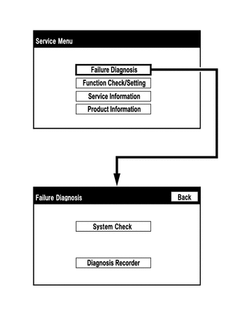
5. SYSTEM CHECK
(a) The "System Check Mode" screen will be displayed by pressing the "System Check" switch on the "Failure Diagnosis" screen.
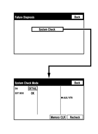
6. CHECK DTC (CHECK USING SYSTEM CHECK MODE SCREEN)
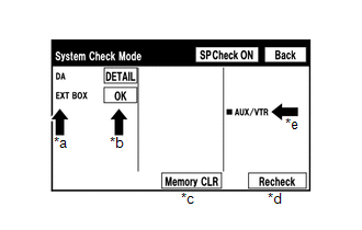
(a) System check mode screen description
 Screen Description
|
Display |
Content |
|---|---|
|
*a: Device Name List No. 1 |
|
|
*b: Check Result |
Result codes for all devices are displayed. |
|
*c: Memory Clear |
|
|
*d: Recheck |
|
|
*e: Device Name List No. 2 |
|
|
Name |
Component |
Connection Method |
|---|---|---|
|
DA |
Radio and display receiver assembly |
- |
|
EXT BOX*1 |
Stereo component tuner assembly |
Communication line for LVDS |
- *1: w/ SDARS System
|
Result |
Meaning |
Action |
|---|---|---|
|
OK |
The device does not respond with a DTC. |
- |
|
DETAIL |
The device responds with a DTC. |
Look up the DTC in "Unit Check Mode". |
|
NCON |
The device was previously present, but does not respond in diagnostic mode. |
- Check power supply wire harness of the device. - Check the AVC-LAN of the device. |
|
NRES |
The device responds in diagnostic mode, but gives no DTC information. |
- Check power supply wire harness of the device. - Check the AVC-LAN of the device. |
|
Name |
Component |
Connection Method |
|---|---|---|
|
AUX/VTR |
No. 1 stereo jack adapter assembly |
Vehicle wire harness |
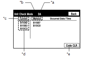
(b) Unit check mode screen description
 Screen Description
|
Display |
Content |
|---|---|
|
*a: Device name |
Target device |
|
*b: History DTC |
Diagnostic memory results and stored DTCs are displayed. |
|
*c: Current DTC |
DTCs output in the service check are displayed. |
|
*d: DTC |
DTC (Diagnostic Trouble Code) |
|
*e: Diagnosis clear switch |
Pushing this switch for 3 seconds clears the diagnostic memory data of the target device (Both response to diagnostic system check result and the displayed data are cleared.). |
HINT:
- This screen is updated once per second.
- A maximum of 6 DTCs can be displayed for history and present DTCs.
(c) Read the system check result.
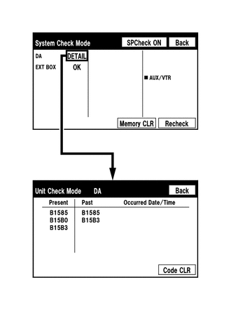
(1) If the check result is "DETAIL", touch the displayed check result to view the results on the "Unit Check Mode" screen and record them.
NOTICE:
A maximum of 6 DTCs can be displayed for history and present DTCs on the "Unit check mode" screen. Therefore, when 6 DTCs are displayed, troubleshoot those DTCs first and then check the "Unit check mode" screen again to see if any other DTCs are displayed.
HINT:
- When all results are "OK", this means that no DTCs are present.
- When proceeding to view the results of another device, press the "Back" switch to return to the "System Check Mode" screen. Repeat the step above to view the results of other devices.
(2) Check the details of the DTC(s) (See page
).
7. DTC CLEAR/RECHECK (CLEAR USING SYSTEM CHECK MODE SCREEN)
(a) Clear DTCs
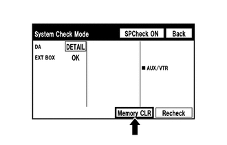
(1) Press the "Memory CLR" switch for 3 seconds.
(2) Confirm that the check results are cleared.
HINT:
- To clear the DTCs for a specific device, clear the DTCs using the "Unit Check Mode" screen.
- When clearing the DTCs using the "Unit Check Mode" screen, press the "Code CLR" switch for 3 seconds.
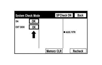
(b) Recheck
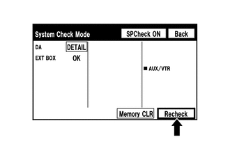
(1) Press the "Recheck" switch.
(2) Confirm that all diagnostic codes are "OK" when the check results are displayed. If a code other than "OK" is displayed, troubleshoot again.
HINT:
When DTCs are cleared using the "Unit Check Mode" screen, press the "Back" switch to return to the "System Check Mode" screen and perform this operation.
8. FINISH DIAGNOSTIC MODE
(a) Turn the ignition switch off.
 Terminals Of Ecu
TERMINALS OF ECU
1. RADIO AND DISPLAY RECEIVER ASSEMBLY
Terminal No. (Symbol)
Wiring Color
Terminal Description
Condition
Specified Condition ...
 Diagnostic Trouble Code Chart
DIAGNOSTIC TROUBLE CODE CHART
Audio and Visual System
DTC Code
Detection Item
See page
B1324
Lost Communication with Meter
...
Other materials:
Installation
INSTALLATION
CAUTION / NOTICE / HINT
CAUTION:
Some of these service operations affect the SRS airbag system. Read the precautionary
notices concerning the SRS airbag system before servicing (See page
).
HINT:
Use the same procedure for both the RH and LH sides.
The procedure des ...
Abnormal Change in Output Signal of Front Speed Sensor RH (Test Mode DTC) (C1275,...,C1414)
DESCRIPTION
Refer to DTCs C1401 and C1402 (See page ).
DTC Code
DTC Detection Condition
Trouble Area
C1275
C1276
Stored only during test mode.
Front speed sensor RH/LH
Front speed sensor rotor RH/LH (Front ...
Data List / Active Test
DATA LIST / ACTIVE TEST
1. DATA LIST
HINT:
Using the Techstream to read the Data List allows values or states of switches,
sensors, actuators and other items to be read without removing any parts. This non-intrusive
inspection can be very useful because intermittent conditions or signals may ...
