Toyota Tacoma (2015-2018) Service Manual: Inspection
INSPECTION
PROCEDURE
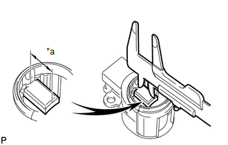
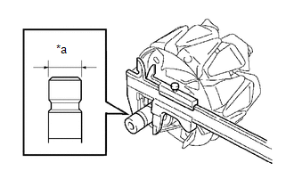
1. INSPECT GENERATOR BRUSH HOLDER ASSEMBLY
|
(a) Using a vernier caliper, measure the brush length. Text in Illustration
Standard exposed length: 9.5 to 11.5 mm (0.374 to 0.453 in.) Minimum exposed length: 4.5 mm (0.177 in.) If the brush length is less than the minimum, replace the generator brush holder assembly. |
|
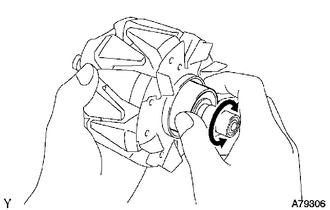
2. INSPECT GENERATOR ROTOR ASSEMBLY
|
(a) Check that the generator rotor bearing is not rough or worn. If necessary, replace the generator rotor assembly. |
|
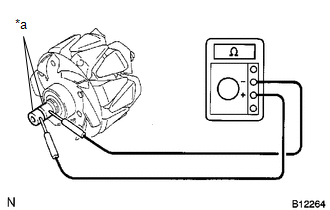
(b) Check the generator rotor assembly for an open circuit.
|
(1) Measure the resistance according to the value(s) in the table below. Text in Illustration
Standard Resistance:
If the result is not as specified, replace the generator rotor assembly. |
|
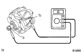
(c) Check the generator rotor assembly for an open circuit.
|
(1) Measure the resistance according to the value(s) in the table below. Text in Illustration
Standard Resistance:
If the result is not as specified, replace the generator rotor assembly. |
|
|
(d) Using a vernier caliper, measure the slip ring diameter. Text in Illustration
Standard diameter: 14.2 to 14.8 mm (0.559 to 0.583 in.) Minimum diameter: 14.0 mm (0.551 in.) If the diameter is less than the minimum, replace the generator rotor assembly. |
|
 Disassembly
DISASSEMBLY
PROCEDURE
1. REMOVE GENERATOR PULLEY
(a) Mount the generator assembly in the vise between aluminum plates.
NOTICE:
Do not overtighten the vise.
(b) Install SST 1-A to the generator p ...
 Installation
INSTALLATION
PROCEDURE
1. INSTALL GENERATOR ASSEMBLY
(a) Install the generator bracket to the generator assembly with the bolt.
Torque:
20 N·m {204 kgf·cm, 15 ft·lbf}
(b) Install the generat ...
Other materials:
Open in ABS Solenoid Relay Circuit (C146E,C146F)
DESCRIPTION
The ABS solenoid relay supplies power to the ABS solenoid and TRAC solenoid.
The solenoid relay is turned on 1.5 seconds after the ignition switch is turned
ON, and is turned off if an open or short in the solenoid is detected by the self
diagnosis performed when the engine starts ...
Disposal
DISPOSAL
CAUTION / NOTICE / HINT
CAUTION:
Before performing pre-disposal deployment of any SRS part, review and closely
follow all applicable environmental and hazardous material regulations. Pre-disposal
deployment may be considered hazardous material treatment.
PROCEDURE
1. PRECAUTION
...
Main Body ECU Vehicle Information Reading/Writing Process Malfunction (B15F6)
DESCRIPTION
This DTC is stored when items controlled by the main body ECU (multiplex network
body ECU) cannot be customized via the audio and visual system vehicle customization
screen.
HINT:
The main body ECU (multiplex network body ECU) controls the items for the following
systems th ...
