Toyota Tacoma (2015-2018) Service Manual: Removal
REMOVAL
PROCEDURE
1. PRECAUTION
NOTICE:
After turning the ignition switch off, waiting time may be required before disconnecting the cable from the negative (-) battery terminal. Therefore, make sure to read the disconnecting the cable from the negative (-) battery terminal notices before proceeding with work.
Click here .gif)
2. DISCONNECT CABLE FROM NEGATIVE BATTERY TERMINAL
NOTICE:
When disconnecting the cable, some systems need to be initialized after the cable is reconnected.
Click here
3. DISCONNECT CABLE FROM POSITIVE BATTERY TERMINAL
4. REMOVE BATTERY CLAMP SUB-ASSEMBLY
(a) Loosen the nut and remove the battery clamp sub-assembly.
5. REMOVE BATTERY
6. REMOVE BATTERY TRAY
7. REMOVE V-BANK COVER
Click here
8. REMOVE FAN AND GENERATOR V BELT
Click here
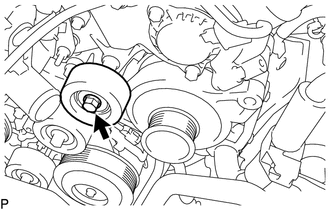
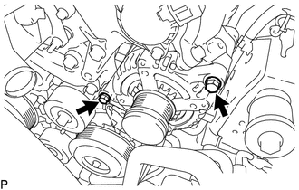
9. REMOVE NO. 2 IDLER PULLEY SUB-ASSEMBLY
|
(a) Remove the bolt and No. 2 idler pulley sub-assembly. |
|
10. REMOVE NO. 1 SURGE TANK STAY
Click here
11. REMOVE GENERATOR ASSEMBLY
|
(a) Disengage the clamp and disconnect the engine wire from the wire harness clamp bracket. |
|
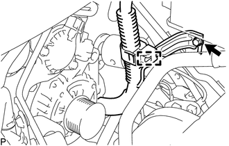
(b) Remove the bolt and wire harness clamp bracket.
|
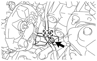
(c) Disconnect the connector from the generator assembly. |
|
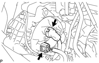
(d) Remove the terminal cap.
(e) Remove the nut and disconnect the engine wire from the terminal B.
|
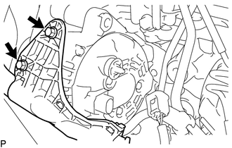
(f) Remove the 2 bolts and disconnect the engine wire from the generator assembly. |
|
|
(g) Disengage the clamp and disconnect the engine wire from the wire harness clamp bracket |
|
(h) Remove the bolt and disconnect the generator bracket from the cylinder block sub-assembly.
|
(i) Remove the 2 bolts and generator assembly. |
|
|
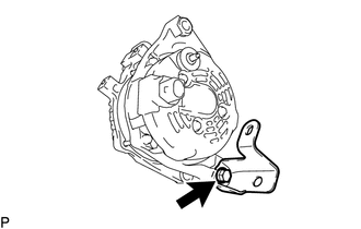
(j) Remove the bolt and generator bracket from the generator assembly. |
|
 Components
COMPONENTS
ILLUSTRATION
ILLUSTRATION
...
 Disassembly
DISASSEMBLY
PROCEDURE
1. REMOVE GENERATOR PULLEY
(a) Mount the generator assembly in the vise between aluminum plates.
NOTICE:
Do not overtighten the vise.
(b) Install SST 1-A to the generator p ...
Other materials:
Satellite Radio Tuner
Components
COMPONENTS
ILLUSTRATION
Removal
REMOVAL
PROCEDURE
1. REMOVE RADIO AND DISPLAY RECEIVER ASSEMBLY WITH BRACKET
(See page )
2. REMOVE NO. 1 NAVIGATION WIRE
(a) Disconnect the 6 connectors to remove the No. 1 navigation wire.
...
Installation
INSTALLATION
PROCEDURE
1. INSTALL HAZARD WARNING SIGNAL SWITCH ASSEMBLY (AIR CONDITIONING CONTROL ASSEMBLY)
(for Automatic Air Conditioning System)
(a) Connect the connectors.
(b) Engage the 8 clips to hazard warning signal switch assembly (air conditioning
control assembly).
2. INSTALL HAZ ...
Freeze Frame Data
FREEZE FRAME DATA
1. FREEZE FRAME DATA
HINT:
Whenever a DTC is detected or the ABS operates, the skid control ECU
stores the current vehicle (sensor) state as freeze frame data.
The skid control ECU stores the number of times (maximum: 31) the ignition
switch has been turned f ...
